An ultra-low power lithium battery protection circuit

A protection circuit, ultra-low power consumption technology, applied in the direction of battery overcharge protection, battery disconnection circuit, battery circuit device, etc., can solve the problem of lithium battery voltage drop too fast, affecting customer experience, affecting battery performance and life, etc. problem, to achieve the effect of ultra-low average power consumption

Active Publication Date: 2021-05-04
SUZHOU XYSEMI ELECTRONICS TECH CO LTD
View PDF2 Cites 0 Cited by
  • Summary
  • Abstract
  • Description
  • Claims
  • Application Information

AI Technical Summary

Problems solved by technology

After the lithium battery and the lithium battery protection chip are connected, the lithium battery protection chip has been consuming the current of the lithium battery. Since the capacity of the lithium battery is getting smaller and smaller, the working current of the lithium battery protection chip is required to be smaller and smaller, otherwise It is easy to cause the voltage of the lithium battery to drop too fast, resulting in a decrease in the capacity of the battery, affecting the customer experience, and seriously affecting the performance and life of the battery

Method used


Image

  • An ultra-low power lithium battery protection circuit
  • An ultra-low power lithium battery protection circuit
  • An ultra-low power lithium battery protection circuit

Examples


Embodiment 1

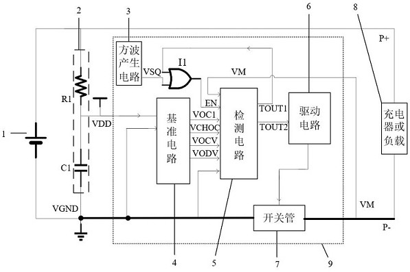
[0036]Such asfigure 1 As shown, the present application provides an ultra-low power consuming lithium battery protection circuit including a battery 1, a filter circuit 2, a lithium battery protection chip 9, and a charger or load 8, wherein:

[0037]The filter circuit 2 includes a first resistor R1 and a first capacitor C1, and the battery 1 is connected to the first electrical resistance R1 and the positive electrode P + of the charger or the load 8, the first resistor R1 is connected to the first capacitor C1 end, VDD end and reference The second input of the circuit 4, the first capacitor C1 connects the third input of the reference circuit 4, the ground end of the circuit 5, and the second end of the switch pipe 7.

[0038]The lithium battery protective chip 9 includes a square wave generating circuit 3, a first or gate I1, a reference circuit 4, a detecting circuit 5, a drive circuit 6, and a switch tube 7, wherein:

[0039]The square wave generating circuit 3 is used to generate a squ...

Embodiment 2

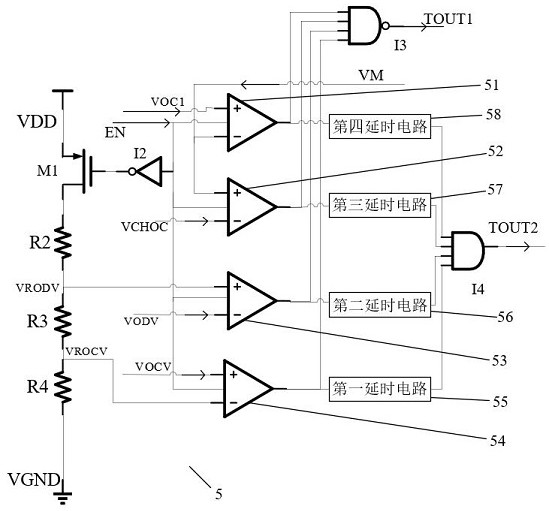
[0054]Such asfigure 2 As shown, the difference between the present embodiment and the embodiment is that the connection of the detecting circuit 5 is disconnected from the first input of the reference circuit 4, i.e., only the detection circuit 5 is controlled by the square wave generating circuit 3. The working current of the lithium battery protective chip 9 in the examples is higher than the operating current of the first embodiment, but is lower than the conventional lithium electricity protection circuit operating current.


PUM


Abstract

The invention discloses a lithium battery protection circuit with ultra-low power consumption, including a battery, a filter circuit, a lithium battery protection chip and a charger or a load, wherein: the lithium battery protection chip includes a square wave generation circuit, a first OR gate, a reference circuit, detection circuit, drive circuit, switch tube, wherein: the square wave generating circuit is used to generate a square wave signal to control the working time of the reference circuit and the detection circuit; the reference circuit is used to generate the voltage and Current; the detection circuit is used to judge the working state of the lithium battery protection chip, and the working state includes normal state, overcharge voltage state, overdischarge voltage state, discharge overcurrent state, and charge overcurrent state; The switch signal generated inside the protection chip controls the switch tube to be turned on or off. The invention reduces the average current consumed by the lithium battery protection circuit by turning on at least some circuits at intervals during normal operation.

Description

Technical field[0001]The present invention relates to the field of lithium battery protection, and more particularly to a low-power lithium battery protection circuit.Background technique[0002]With the development of e-technology in the twentieth century, the lithium battery has entered a large-scale practical phase, and the miniaturized equipment is increasing, requiring the capacity of lithium batteries to smaller, especially in TWS, smart bracelet watches, etc. In the middle, the capacity of the lithium battery may only be several tens of MAH, or even as low as many MAH.[0003]In the prior art, the lithium electrical protection circuit can be divided into four modules: a reference circuit, a detection circuit, a drive circuit, a switch tube. The drive circuit is a logic control circuit, and the current is not consumed during normal operation; the switch tube is a MOS tube, which does not consume current when turning on or off. Therefore, the current consumption module is a referen...

Claims


Application Information

Patent Timeline
Patent Type & Authority Patents(China)
IPC IPC(8): H02H7/18H02J7/00
CPCH02H7/18H02J7/0029H02J7/0031H02J7/0068H02J7/00302H02J7/00304H02J7/00306
Inventor 蒋锦茂崔国庆龚坤林
Owner SUZHOU XYSEMI ELECTRONICS TECH CO LTD
Why Eureka
Try Eureka