
Power tube structure and power converter

A power converter and power tube technology, which is applied in the direction of converting AC power input into DC power output, output power conversion devices, and structural components of conversion equipment, etc. 101 Welding holes cannot be aligned, etc.

Active Publication Date: 2021-02-23
合肥阳光电动力科技有限公司
View PDF5 Cites 1 Cited by
  • Summary
  • Abstract
  • Description
  • Claims
  • Application Information

AI Technical Summary

Problems solved by technology

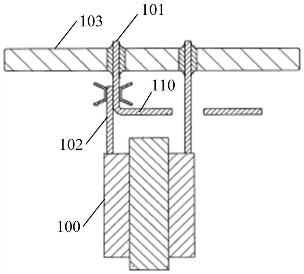
[0003] However, in practical applications, it is found that when the source pin 102 of the transistor is welded to the fin 101 on the power bus bar 110, the fin 101 on the power bus bar 110 is easily deformed, which may cause The fins 101 cannot be aligned with the corresponding soldering holes on the circuit board 103. If the distance between the two is too large, the installation and connection cannot be completed.

Method used


Image

  • Power tube structure and power converter
  • Power tube structure and power converter
  • Power tube structure and power converter

Examples


Embodiment Construction

[0045] The following will clearly and completely describe the technical solutions in the embodiments of the application with reference to the drawings in the embodiments of the application. Apparently, the described embodiments are only some of the embodiments of the application, not all of them. Based on the embodiments in this application, all other embodiments obtained by persons of ordinary skill in the art without creative efforts fall within the protection scope of this application.

[0046] In this application, relational terms such as first and second, etc. are only used to distinguish one entity or operation from another entity or operation, and do not necessarily require or imply any relationship between these entities or operations. an actual relationship or order. Moreover, the term "comprises", "comprises" or any other variation thereof is intended to cover a non-exclusive inclusion such that a process, method, article or apparatus comprising a set of elements inc...


PUM


Abstract

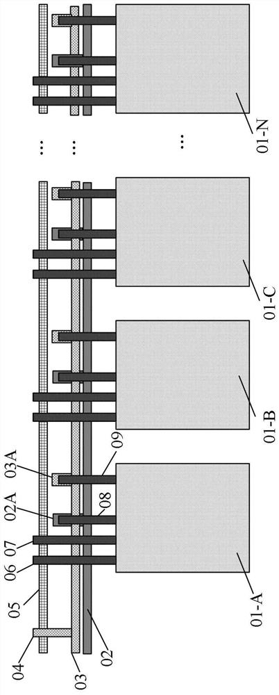
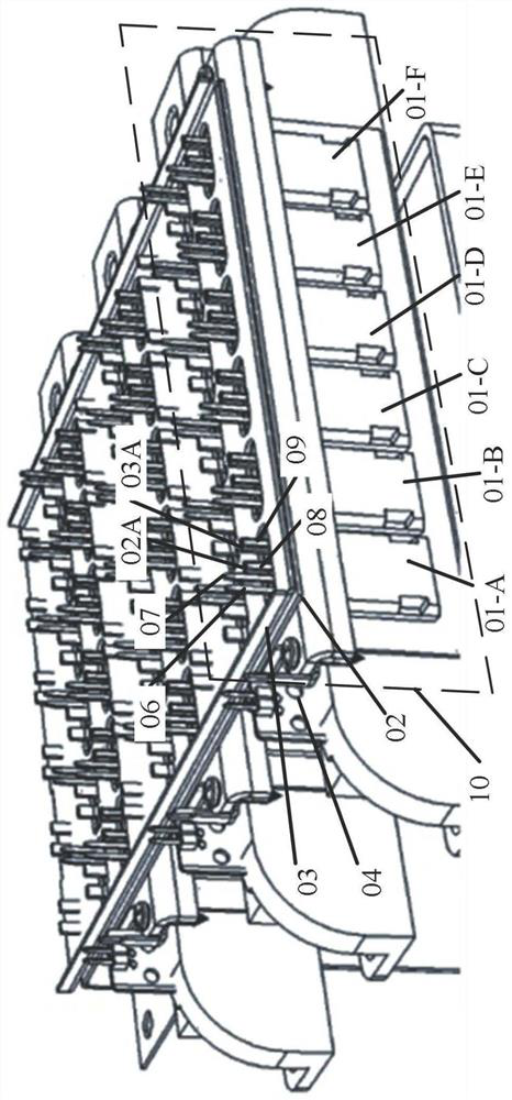
The invention provides a power tube structure and a power converter. The power converter comprises at least one transistor. In the power tube structure, each transistor is packaged by adopting 4-PIN,and a packaging pin of each transistor comprises a signal source electrode pin, a power source electrode pin, a drain electrode pin and a gate electrode pin; wherein the source electrode pins of the transistor are divided into a power source electrode pin and a signal source electrode pin, so that the transistor realizes the connection between the source electrode of the transistor and a circuit board and the connection between the transistor and a corresponding power busbar through the power source electrode pin and the signal source electrode pin of the transistor; as the connecting points on the pins of the transistor only need to be welded once, the influence of welding deformation on the position relationship between the pins and the corresponding welding holes can be reduced, namely,the influence of welding deformation on the installation and connection among the transistor, the power busbar and the circuit board is reduced; therefore, the installation and connection precision among the transistor, the power busbar and the circuit board can be improved.

Description

technical field [0001] The invention relates to the technical field of power electronics, in particular to a power tube structure and a power converter. Background technique [0002] In the structure of multi-tube parallel inverter based on discrete devices, such as figure 1 As shown, the source pin 102 of the transistor 100 is cut short, first soldered to the power bus bar 110 , and then soldered to the circuit board through the fin 101 on the power bus bar 110 . [0003] However, in practical applications, it is found that when the source pin 102 of the transistor is welded to the fin 101 on the power bus bar 110, the fin 101 on the power bus bar 110 is easily deformed, which may cause The fins 101 cannot be aligned with the corresponding soldering holes on the circuit board 103 , and if the distance between them is too large, the installation and connection cannot be completed. Contents of the invention [0004] In view of this, the present invention provides a power ...

Claims


Application Information

Patent Timeline
Patent Type & Authority Applications(China)
IPC IPC(8): H02M1/00H02M7/00H02M7/219H02M7/5387H01L25/07
CPCH02M1/00H02M7/00H02M7/003H02M7/219H02M7/5387H01L25/072Y02B70/10
Inventor 陈文杰吴一凡杜恩利史良辰于安博
Owner 合肥阳光电动力科技有限公司
Learn More