Maximum power point tracking circuit and method of off-grid photovoltaic heat storage system
A technology of maximum power point and tracking circuit, applied in the field of photovoltaics, can solve the problem of large power loss, and achieve the effect of improving economic benefits and reducing photovoltaic power
- Summary
- Abstract
- Description
- Claims
- Application Information
AI Technical Summary
Problems solved by technology
Method used
Image

Examples
no. 1 example
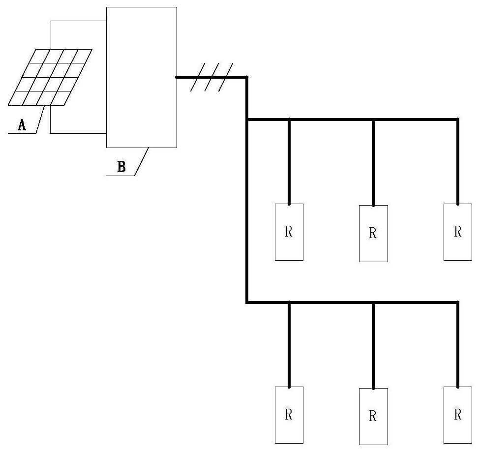
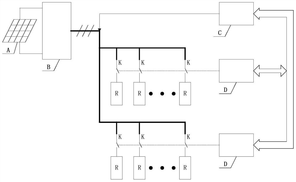
[0052] An embodiment of the present invention discloses a maximum power point tracking circuit of an off-grid photovoltaic heat storage system, such as image 3 As shown, the system includes a photovoltaic panel A, a photovoltaic converter B for converting the direct current output by the photovoltaic panel into an alternating current, and a thermal load R, and the tracking circuit includes:
[0053] Load controller C, N contactors K and M remote IO modules D;
[0054] Wherein, the first end of each contactor in the contactors is connected to the output end of the photovoltaic converter B, and the second end of each contactor is respectively connected to a heat load;
[0055] Each of the remote IO modules D is connected to one or more of the contactors;
[0056] The load controller C is used for sampling the output voltage of the photovoltaic converter B, and according to the comparison between the output voltage and the predetermined voltage, the remote IO module D controls ...
no. 2 example
[0065] Such as Figure 5 As shown, an embodiment of the present invention also discloses an off-grid photovoltaic heat storage system, including
[0066] Photovoltaic panel A;
[0067] Photovoltaic converter B used to convert the direct current output by the photovoltaic panel into alternating current;
[0068] According to the tracking circuit described in the first embodiment; and the thermal load R.
[0069] In a specific embodiment, the tracking circuit includes: a load controller C, 6 contactors K and 2 remote IO modules D.
[0070] When the off-grid photovoltaic heat storage system is running, the load controller C measures the output voltage of the photovoltaic converter B, and the load controller C calculates the output voltage of the photovoltaic converter B based on the measured output voltage through a control algorithm. The number of pull-in contactors K, the load controller C transmits the command to the remote IO module D through communication, and the remote ...
no. 3 example
[0073] Such as Figure 4 As shown, an embodiment of the present invention also discloses a method for controlling the tracking circuit described in the first embodiment, including:
[0074] The photovoltaic cell panel outputs direct current according to light irradiation;
[0075] The photovoltaic converter converts the direct current into alternating current;
[0076] The load controller C samples the AC voltage output by the photovoltaic converter B, and according to the comparison between the AC voltage and a predetermined voltage, enables the remote IO module D to control the pull-in and break-off of the connected contactor, and the thermal load Switching in and out, so as to realize the maximum power point tracking function of the off-grid photovoltaic heat storage system.
[0077] In a specific embodiment, it also includes when the output voltage of the photovoltaic converter B sampled by the load controller C is greater than or equal to the first set voltage U H At t...
PUM
 Abstract
Description
Claims
Application Information
 - R&D Engineer
- R&D Manager
- IP Professional
- Industry Leading Data Capabilities
- Powerful AI technology
- Patent DNA Extraction
Browse by: Latest US Patents, China's latest patents, Technical Efficacy Thesaurus, Application Domain, Technology Topic.
© 2024 PatSnap. All rights reserved.Legal|Privacy policy|Modern Slavery Act Transparency Statement|Sitemap