
Superheterodyne microwave photon receiving system and method

A microwave photonic and receiving system technology, applied in microwave photonics and microwave radio frequency fields, can solve problems such as stray interference, low frequency microwave signals cannot be effectively converted, and achieve small harmonic spurs, good image and intermodulation and other spurs Suppression, effect of large instantaneous bandwidth

Active Publication Date: 2021-02-23
CHINA ACADEMY OF SPACE TECHNOLOGY
View PDF10 Cites 5 Cited by
  • Summary
  • Abstract
  • Description
  • Claims
  • Application Information

AI Technical Summary

Problems solved by technology

[0011] The technical problem to be solved by the present invention is that the existing technology is limited by the ultra-wideband electric local oscillator source, and there are spurious interferences, and the problem that low-frequency microwave signals cannot be effectively converted. The present invention provides an ultra-external The differential microwave photon receiving system makes the receiver have higher comprehensive application performance in terms of operating spectrum range, instantaneous bandwidth, image and spurious suppression, low nonlinearity, etc.

Method used


Image

  • Superheterodyne microwave photon receiving system and method
  • Superheterodyne microwave photon receiving system and method
  • Superheterodyne microwave photon receiving system and method

Examples


Embodiment 1

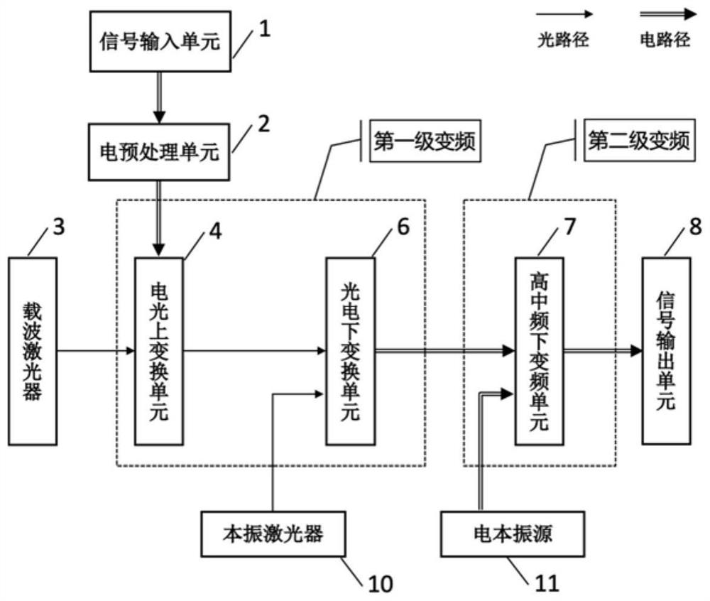
[0049]Such asfigure 1 As shown, the ultra-extraction microwave photon receiving system provided in the embodiment of the present invention includes a signal input unit 1, an electro-optical transmission unit 2, a carrier laser 3, an electro-optic conversion unit 4, a vibration laser 10, and a photovoltaic transform unit 6. , The electricity vibration source 11, high tone frequency downconvert unit 7, and signal output unit 8.

[0050]The signal input unit 1 receives the microwave signal to be detected and input to the electrical pretachment unit 2. The electrical pretachment unit 2 performs the frequency band of the microwave signal to the electro-optic conversion unit 4 after the signal is preselected. The carrier laser 3 generates a phot carrier input to the electro-optic conversion unit 4.

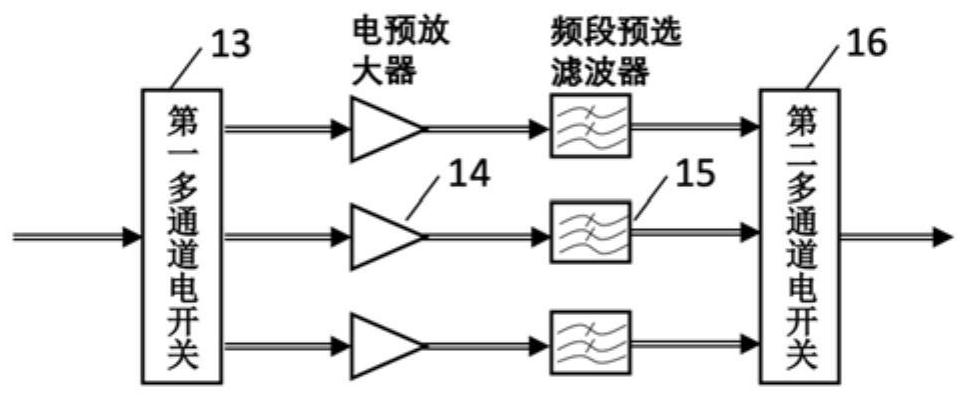
[0051]The electro-optical transform unit 4 converts the input microwave signal to the optical carrier to obtain a light-load microwave signal. The electrical pretachment unit 2 and the carrier lase...

Embodiment 2

[0061]Such asFigure 6 As shown, the second embodiment is substantially the same as that of the Example, the same is not described in the same, and the excessive microwave photon receiving system further includes an photon predecessor unit 5. The photon preprocessing unit 5 is provided between the electro-optic conversion unit 4 and the photovoltaic transform unit 6, and the input light-load microwave signal is photomic to the input photoelectric transform unit 6.

[0062]In some preferred embodiments, the photon predecessor unit 5 includes a light amplifier 20, a first multi-channel optical switch 21, a light filter bank 22, and a second multi-channel optical switch 23, a referenceFigure 7 Indicated. The function of the optical amplifier 20 is to amplify the power of the input light carrier microwave signal. The action of the first multi-channel optical switch 21 is to divide the input light carrier microwave signal into several optical pretreatment channels. The function of the optica...

Embodiment 3

[0067]Such asFigure 9 As shown, the third embodiment is substantially the same as that of the Example, the same is not described in the same, and the extra-extraction microwave photon receiving system further includes a pipe control unit 9.

[0068]The optical carriers and full-optical vibrations employed in the present invention are produced by two separate lasers, respectively. Since the two independently running lasers are non-related, the relative frequency and phase relationship between the optical carriers and the full-optical vibrations are uncertain, and the high multi-frequency signal generated by the first stage variable frequency will contain a light carrier. The beading and frequency offset error between the full-optical local oscillator, so the frequency and phase of the optical carrier and the full-optical vibration must be performed on the optical carrier and the full-optical vibration. In the present invention, the control unit 9 is used to monitor the parameter state o...


PUM


Abstract

The invention relates to a superheterodyne microwave photon receiving system which comprises an electric preprocessing unit, a carrier laser, an electro-optic up-conversion unit, a local oscillator laser, a photoelectric down-conversion unit, an electric local oscillator source, a high-intermediate frequency down-conversion unit and the like. The electric preprocessing unit is used for carrying out frequency band pre-selection filtering on a to-be-measured microwave signal and then inputting the signal into the electro-optical up-conversion unit. The electro-optical up-conversion unit is usedfor up-converting the microwave signal to an optical carrier output by the carrier laser to obtain an optical carrier microwave signal; the local oscillator laser is used for generating an all-opticallocal oscillator; the photoelectric down-conversion unit is used for down-converting the optical carrier microwave signal into a high-intermediate frequency signal by using an all-optical local oscillator; the electric local oscillator source is used for generating a high-intermediate frequency electric local oscillator; and the high-intermediate frequency down-conversion unit is used for down-converting the high-intermediate frequency signal into a low-intermediate frequency signal or a baseband signal. According to the invention, a two-stage frequency conversion mode is utilized, and an ultra-wideband all-optical local oscillator is combined to replace the traditional pure electric frequency conversion and microwave photon frequency conversion modes, so that the frequency conversion technical bottleneck in the ultra-wideband receiving technology is solved.

Description

Technical field[0001]The present invention relates to the field of microwave photons and microwave radio frequency technologies, and more particularly to an ultra-extraortary phase microwave photon receiving system and method.Background technique[0002]The current receiver system is a traditional pure electronic device and technology, and a typical system architecture has two categories: heterodyne architecture and zero difference architecture. The heterodyne architecture changes the microwave signal to low intermediate frequency, has a good mirroring and other spurious suppression capabilities and a large dynamic range, but the system is complex, the instantaneous band is small, often used by high-end equipment such as spectrum analyzers. The zero difference architecture directs the microwave signal to the baseband, the structure is simple, the instantaneous bandwidth is large, but the murdion of mirroring is poor, the dynamic range is smaller, and is often used by a communication r...

Claims


Application Information

Patent Timeline
Patent Type & Authority Applications(China)
IPC IPC(8): H04B10/64H04B10/61
CPCH04B10/6164H04B10/6165H04B10/64
Inventor 高光宇梁启军刘乃金彭焕发刘紫玉
Owner CHINA ACADEMY OF SPACE TECHNOLOGY
Learn More