A superheterodyne microwave photon receiving system and method

A microwave photon and receiving system technology, applied in the field of microwave photon and microwave radio frequency, can solve the problems of spurious interference and low-frequency microwave signal ineffective frequency conversion, etc., and achieve large frequency conversion range, good image and intermodulation and other spurious suppression, The effect of spurious suppression such as good image

Active Publication Date: 2021-10-29
CHINA ACADEMY OF SPACE TECHNOLOGY
View PDF0 Cites 0 Cited by
  • Summary
  • Abstract
  • Description
  • Claims
  • Application Information

AI Technical Summary

Problems solved by technology

[0011] The technical problem to be solved by the present invention is that the existing technology is limited by the ultra-wideband electric local oscillator source, and there are spurious interferences, and the problem that low-frequency microwave signals cannot be effectively converted. The present invention provides an ultra-external The differential microwave photon receiving system makes the receiver have higher comprehensive application performance in terms of operating spectrum range, instantaneous bandwidth, image and spurious suppression, low nonlinearity, etc.

Method used


Image

  • A superheterodyne microwave photon receiving system and method
  • A superheterodyne microwave photon receiving system and method
  • A superheterodyne microwave photon receiving system and method

Examples


Embodiment 1

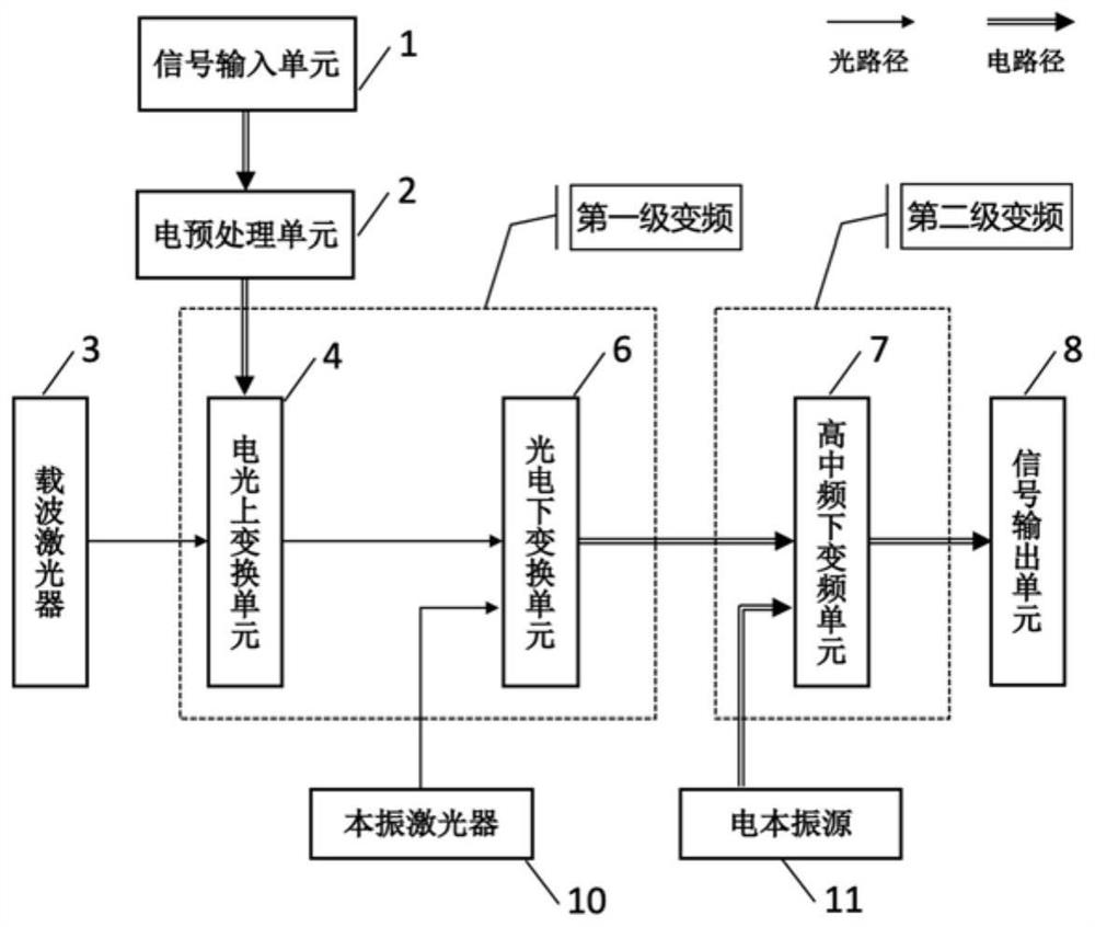
[0049] Such as figure 1 As shown, the superheterodyne microwave photon receiving system provided by Embodiment 1 of the present invention includes a signal input unit 1, an electrical preprocessing unit 2, a carrier laser 3, an electro-optical up-conversion unit 4, a local oscillator laser 10, and an opto-electronic down-conversion unit 6 , an electric local oscillator source 11 , an intermediate frequency down-conversion unit 7 , and a signal output unit 8 .

[0050] Wherein, the signal input unit 1 receives the microwave signal to be detected and inputs it to the electrical preprocessing unit 2 . The electrical preprocessing unit 2 performs frequency band preselection filtering on the microwave signal and then inputs it to the electro-optical up-conversion unit 4 . The carrier laser 3 generates an optical carrier to be input to the electro-optical up-conversion unit 4 .

[0051] The electro-optical up-conversion unit 4 up-converts the input microwave signal to the optical ...

Embodiment 2

[0061] Such as Figure 6 As shown, the second embodiment is basically the same as the first embodiment, and the similarities will not be repeated. The difference is that the superheterodyne microwave photon receiving system further includes a photon preprocessing unit 5 . The photon pre-processing unit 5 is arranged between the electro-optic up-conversion unit 4 and the photo-optic down-conversion unit 6 , and performs photon pre-processing on the input optical-carrying microwave signal before inputting it into the photo-optic down-conversion unit 6 .

[0062] In some preferred embodiments, the photon preprocessing unit 5 includes: an optical amplifier 20, a first multi-channel optical switch 21, an optical filter bank 22 and a second multi-channel optical switch 23, referring to Figure 7shown. The function of the optical amplifier 20 is to amplify the power of the input optical-carrying microwave signal. The function of the first multi-channel optical switch 21 is to split...

Embodiment 3

[0067] Such as Figure 9 As shown, the third embodiment is basically the same as the first embodiment, and the similarities will not be repeated. The difference is that the superheterodyne microwave photon receiving system further includes a management and control unit 9 .

[0068] The optical carrier and the all-optical local oscillator used in the present invention are respectively generated by two independent lasers. Since the two independently operating lasers are non-correlated, the relative frequency and phase relationship between the optical carrier output by them and the all-optical local oscillator is uncertain, and the high-frequency signal generated by the first-stage frequency conversion will contain the optical carrier The beat frequency phase noise and frequency offset error between the optical carrier and the all-optical local oscillator, so to achieve high-performance microwave signal down-conversion reception, it is necessary to correlate the frequency and pha...


PUM


Abstract

The invention relates to a superheterodyne microwave photon receiving system, which includes an electrical preprocessing unit, a carrier laser, an electro-optical up-conversion unit, a local oscillator laser, a photoelectric down-conversion unit, an electrical local oscillator source, an intermediate frequency down-conversion unit, etc.; The processing unit is used to pre-select and filter the frequency band of the microwave signal to be tested and then input it to the electro-optic up-conversion unit; the electro-optic up-conversion unit is used to up-convert the microwave signal to the optical carrier output by the carrier laser to obtain the optical carrier microwave signal; the local oscillator laser is used for Generate all-optical local oscillator; the photoelectric down-conversion unit is used to use all-optical local oscillator to down-convert the optical microwave signal to high-frequency signal; the electric local oscillator source is used to generate high-frequency electric local oscillator; the high-frequency down-conversion unit is used Down-convert IF signals to low IF or baseband. The invention uses a two-stage frequency conversion method, combined with an ultra-wideband all-optical local oscillator, to replace the traditional pure electric frequency conversion and microwave photon frequency conversion methods, and solves the bottleneck of the frequency conversion technology in the ultra-wideband receiving technology.

Description

technical field [0001] The invention relates to the technical fields of microwave photons and microwave radio frequencies, in particular to a superheterodyne microwave photon receiving system and method. Background technique [0002] The current receiver system is traditionally based on pure electronic devices and technologies, and its typical system architecture has two types: heterodyne architecture and homodyne architecture. The heterodyne architecture down-converts the microwave signal to a low-intermediate frequency. It has good spurious suppression capabilities such as images and a large dynamic range, but the system is complex and the instantaneous bandwidth is small, so it is often used by high-end equipment such as spectrum analyzers. The homodyne architecture directly down-converts the microwave signal to the baseband. It has a simple structure and a large instantaneous bandwidth, but it has poor spurious suppression capabilities such as images and a small dynamic ...

Claims


Application Information

Patent Timeline
Patent Type & Authority Patents(China)
IPC IPC(8): H04B10/64H04B10/61
CPCH04B10/6164H04B10/6165H04B10/64
Inventor 高光宇梁启军刘乃金彭焕发刘紫玉
Owner CHINA ACADEMY OF SPACE TECHNOLOGY
Why Eureka
Try Eureka