Environment-friendly spraying device

A spraying device, an environmentally friendly technology, applied in the field of environmentally friendly spraying devices, can solve the problems of environmental pollution, slow spraying efficiency, and inability to guarantee the spraying effect of the workpiece surface

Pending Publication Date: 2021-02-26
德庆县智联机械科技有限公司
View PDF0 Cites 6 Cited by
  • Summary
  • Abstract
  • Description
  • Claims
  • Application Information

AI Technical Summary

Problems solved by technology

[0002] Due to the requirements of the production and processing technology of the workpiece, it needs to be painted on the surface before leaving the factory. On the one hand, the paint is used to isolate the workpiece from the external oxides to achieve a good anti-corrosion effect. On the other hand, it plays the role of coloring and beautification. In the process of spraying the workpiece, the paint needs to be evenly sprayed on the surface of the workpiece. The current spraying method is manual spraying with a paint spray gun, but this method has high requirements for operators, and the...

Method used


Image

  • Environment-friendly spraying device
  • Environment-friendly spraying device
  • Environment-friendly spraying device

Examples


Embodiment 1

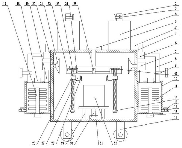
[0019] see Figure 1~Figure 3 As shown, an environment-friendly spraying device includes a processing box 1, a thrust ball bearing 29 is symmetrically arranged on the inner wall of the bottom end of the processing box 1, a workbench 31 is arranged on the top of the thrust ball bearing 29, and a middle inner wall of the bottom end of the processing box 1 Executing motor 30 is arranged on top, and the output end of executing motor 30 is connected with the outer wall of the middle part of the bottom end of workbench 31. The top of workbench 31 is provided with workpiece 32. A support seat 22 is arranged on the top, and the support seat 22 is located inside the processing box 1. The left and right ends of the inner wall of the top of the support seat 22 are symmetrically provided with the execution screw 23 through the bearing seat, and the execution screw 23 penetrates the inner wall of the bottom end of the support seat 22 and extends to Externally, the bottom end of the executi...

Embodiment 2

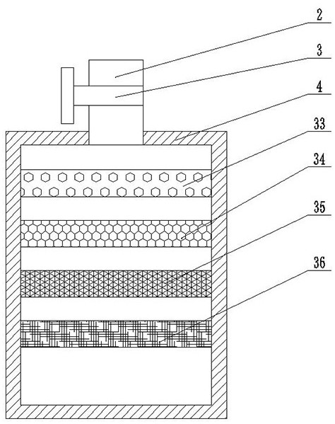
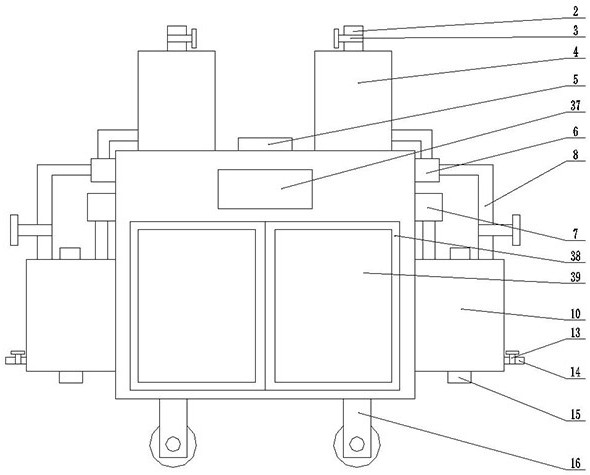
[0024] On the basis of embodiment one, refer to image 3 , a control panel 37 is provided on the front top outer wall of the processing box 1, a warehouse door 38 is arranged on the front bottom outer wall of the processing box 1, and a transparent glass window 39 is inlaid on the front side outer wall of the warehouse door 38; by setting the control panel 37 can realize intelligent control, reduce manpower operation, improve work efficiency, be convenient to take workpiece 16 by arranging warehouse door 38, be convenient to observe the working situation inside processing box 1 by arranging transparent glass window 39.

[0025]Working principle: in the process of use, by setting the rotating motor 5, the support base 22, the execution screw 23, the double-axis motor 25, the first gear 24, the second gear 41, the sleeve 26, the paint box 27, the paint spraying head 28 and Block 12 makes the spraying head 28 move in a circle while moving in the vertical direction, so that the su...


PUM


Abstract

The invention relates to the technical field of paint spraying, in particular to an environment-friendly spraying device which comprises a machining box, thrust ball bearings are symmetrically arranged on the inner wall of the bottom end of the machining box, and a workbench is arranged at the top ends of the thrust ball bearings; an execution motor is arranged on the inner wall of the middle of the bottom end of the machining box, and the output end of the execution motor is connected with the outer wall of the bottom end of the workbench; and a machined part is arranged at the top of the workbench. The environment-friendly spraying device is simple in structure, by arranging a rotating motor, a supporting base, execution screws, a double-shaft motor, a first gear, a second gear, sleeves,paint boxes, paint spraying heads and check blocks, the paint spraying heads move in the vertical direction and performs circular motion at the same time, the surface of the machined part is sprayedmore uniformly, the spraying efficiency is high, the paint spraying effect is guaranteed, and the working efficiency is improved.

Description

technical field [0001] The invention relates to the technical field of paint spraying, in particular to an environment-friendly spraying device. Background technique [0002] Due to the requirements of the production and processing technology of the workpiece, it needs to be painted on the surface before leaving the factory. On the one hand, the paint is used to isolate the workpiece from the external oxides to achieve a good anti-corrosion effect. On the other hand, it plays the role of coloring and beautification. In the process of spraying the workpiece, the paint needs to be evenly sprayed on the surface of the workpiece. The current spraying method is manual spraying with a paint spray gun, but this method has high requirements for operators, and the quality of manual spraying is poor. At the same time, labor intensity and a larger workload. [0003] Existing spraying device has the following problems: a: existing spraying device is not only slow in spraying efficiency...

Claims


Application Information

Patent Timeline
IPC IPC(8): B05B16/40B05B13/04B05B14/40B05B14/43B05B15/25B01D50/00B01D53/00B01D53/04B01D53/78B01D53/86
CPCB05B16/40B05B13/041B05B13/0426B05B15/25B05B14/40B05B14/43B01D53/04B01D53/78B01D53/007B01D53/86B01D2253/102B01D2257/91B01D2258/0258B01D50/60
Inventor 叶卫超
Owner 德庆县智联机械科技有限公司
Why Eureka
Try Eureka