Iron chip clearing and self-locking device adapted to workpieces of different sizes and shapes
A technology that adapts to different, self-locking devices, applied in maintenance and safety accessories, metal processing machinery parts, manufacturing tools, etc., can solve problems such as difficulty in dealing with milling workpieces, hidden safety hazards, and tedious work of cleaning iron filings, reducing work The effect of improving the capacity, improving adaptability, and eliminating potential safety hazards
- Summary
- Abstract
- Description
- Claims
- Application Information
AI Technical Summary
Problems solved by technology
Method used
Image

Examples
Embodiment Construction
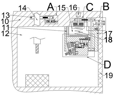
[0023] Combine below Figure 1-8 The present invention is described in detail, wherein, for the convenience of description, the orientations mentioned below are defined as follows: figure 1 The up, down, left, right, front and back directions of the projection relationship itself are the same.
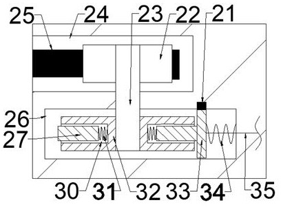
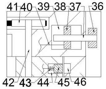
[0024] A chip cleaning and self-locking device adapted to workpieces of different sizes and shapes described in conjunction with accompanying drawings 1-8 includes a numerically controlled milling machine 10, which is provided with a milling cavity 12 opening to the right. The right end of the side wall of the chamber 12 is slidably connected with a dodge door 19, and the upper end wall of the milling chamber 12 is fixedly connected with a large box connection block 17 on the left side of the dodge door 19, and the inside of the large box connection block 17 is There is a large box sliding cavity 15 that penetrates up and down, and a large box 60 is slidably connected between the fron...
PUM
 Abstract
Description
Claims
Application Information
PatSnap Eureka turns technology decisions into work you can execute. Powered by our Innovation Knowledge Graph, it runs expert workflows across engineering, life sciences, materials and intellectual property. Get your review-ready output in minutes.


