Stacking system for metal plate machining

A palletizing system and metal plate technology, applied in the field of palletizing systems for metal plate processing, can solve the problems of inconvenient shifting operations, increased labor intensity of workers, and high prices, so as to avoid mutual collision and mutual extrusion, and improve practicality. High performance and versatility, the effect of ensuring surface flatness

Inactive Publication Date: 2021-02-26
宁波曼汶智能装备有限公司
View PDF0 Cites 4 Cited by
  • Summary
  • Abstract
  • Description
  • Claims
  • Application Information

AI Technical Summary

Problems solved by technology

[0002] In the processing of plates, the processed plates need to be palletized to reduce the occupied area. Traditional palletizing robots are expensive due to their complex mechanism, which discourages small processing plants and can only be replaced by manual labor, which greatly increases labor costs. , increasing the labor intensity of workers
[0003] And for the metal sheet, due to the limited storage or transportation conditions, the surface of the metal sheet is easily deformed and wrinkled. Due to the above phenomenon, on the one hand, the yield rate of the sheet is low, and on the other hand, it is inconvenient. Perform shifting operations, and the specifications of existing palletizing equipment are mostly fixed. Due to the fixed structure, its applicable scenarios and flexibility are limited

Method used


Image

  • Stacking system for metal plate machining
  • Stacking system for metal plate machining
  • Stacking system for metal plate machining

Examples


Embodiment Construction

[0031] The present invention will be further described below in conjunction with the examples.

[0032] The following examples are used to illustrate the present invention, but cannot be used to limit the protection scope of the present invention. The conditions in the embodiment can be further adjusted according to the specific conditions, and the simple improvement of the method of the present invention under the premise of the concept of the present invention belongs to the protection scope of the present invention.

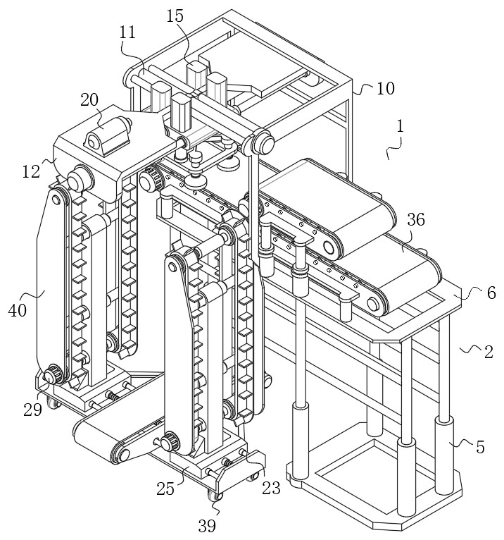
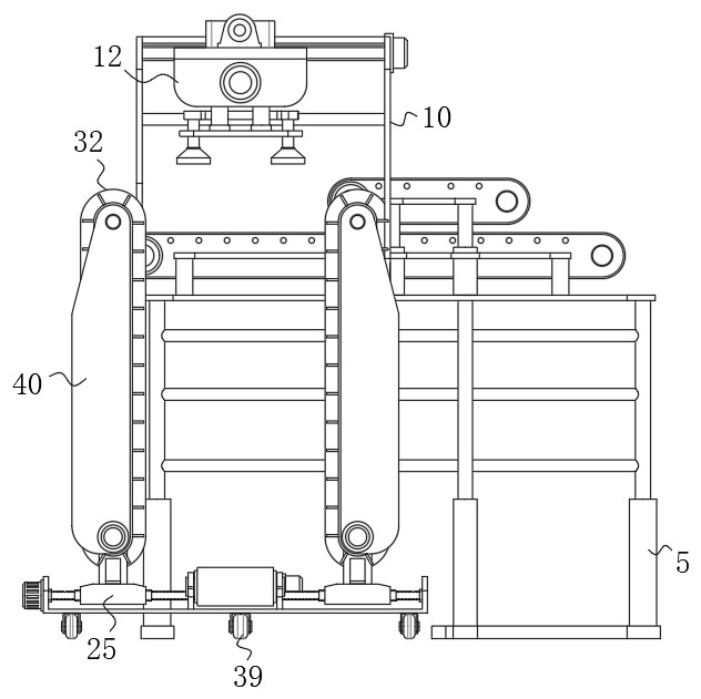
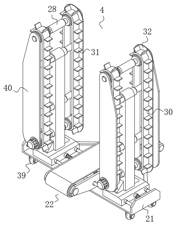
[0033] see Figure 1-8 , the present invention provides a palletizing system for sheet metal processing, comprising a body 1; the body 1 includes a feeding mechanism 2, a material shifting mechanism 3 and a material receiving mechanism 4; the feeding mechanism 2 includes a supporting frame 5, a supporting frame 5 The top surface of the mounting seat 6 is fixedly connected with the mounting seat 6, and the top surface of the mounting seat 6 is fixedly connecte...


PUM


Abstract

The invention discloses a stacking system for metal plate machining, and belongs to the technical field of metal plate machining. The system comprises a body, wherein the body comprises a feeding mechanism, a material moving mechanism and a material receiving mechanism. The feeding mechanism comprises a supporting frame body, wherein the top surface of the supporting frame body is fixedly connected with a mounting base, the top surface of the mounting base is fixedly connected with a lower conveying assembly, the top surface of the lower conveying assembly is fixedly connected with a set of pressing push rods distributed in a rectangular array mode, and the top ends of the set of pressing push rods are fixedly connected with a pressing flattening assembly matched with the lower conveying assembly; the material moving mechanism comprises a connecting frame body. By designing the feeding mechanism, the material moving mechanism and the material receiving mechanism, the device can complete stacking operation of the metal plates in batches in an automatic mode, a fixed specification type structure of traditional stacking arrangement is changed into an adjustable structure, and by adjusting specification, the device can adapt to stacking operation of the plates of multiple specifications.

Description

technical field [0001] The invention belongs to the technical field of sheet metal processing, and in particular relates to a palletizing system for sheet metal processing. Background technique [0002] In the processing of plates, the processed plates need to be palletized to reduce the occupied area. Traditional palletizing robots are expensive due to their complex mechanism, which discourages small processing plants and can only be replaced by manual labor, which greatly increases labor costs. , increasing the labor intensity of workers. [0003] And for the metal sheet, due to the limited storage or transportation conditions, the surface of the metal sheet is easily deformed and wrinkled. Due to the above phenomenon, on the one hand, the yield rate of the sheet is low, and on the other hand, it is inconvenient. For shifting operations, and most of the existing palletizing equipment specifications are fixed, due to the fixed structure, its applicable scenarios and flexib...

Claims


Application Information

Patent Timeline
Patent Type & Authority Applications(China)
IPC IPC(8): B65G57/04B65G47/91B65G37/00B65G17/26B65G17/12B65G17/34B65G41/00
CPCB65G17/12B65G17/26B65G17/34B65G37/00B65G41/003B65G47/912B65G57/04B65G2201/022
Inventor 唐秀恰
Owner 宁波曼汶智能装备有限公司
Why Eureka
Try Eureka