
Fertilizer coating process

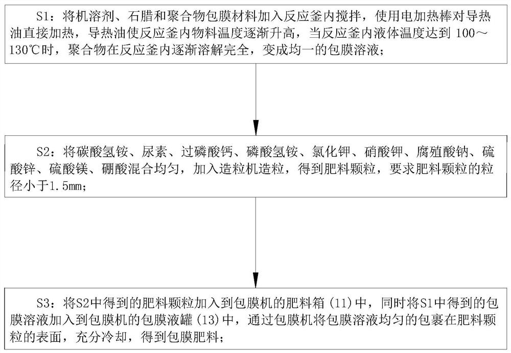
A fertilizer coating and coating technology, which is applied to organic fertilizers, inorganic fertilizers, ammonium salt fertilizers, etc., can solve the problems of poor film thickness uniformity, difficulty in controlling the thickness of the coating, and difficulty in controlling the fertilizer effect time of coated fertilizers. To achieve the effect of improving quality stability, improving coating efficiency and realizing effective control

Inactive Publication Date: 2021-02-26
当涂县江心仁贵家庭农场
View PDF1 Cites 0 Cited by
  • Summary
  • Abstract
  • Description
  • Claims
  • Application Information

AI Technical Summary

Problems solved by technology

[0006] In order to make up for the deficiencies of the prior art and solve the prior art, when coating the fertilizer, a coating machine needs to be used. The coating machine of the prior art adds the coating solution to the fertilizer particles, and then stirs the fertilizer particles , so that the surface of the fertilizer particles adheres to the uniform coating solution. In addition, through the high-pressure tank, the high pressure of the high-pressure tank sprays the coating solution inside the high-pressure tank through the external nozzle and sprays it on the surface of the fertilizer particles to achieve The surface of the fertilizer particles is quickly coated, but the fertilizer particles in the above method are stacked and squeezed on each other. During the coating process, the fertilizer particles collide with each other, and the film thickness uniformity of the coating solution on the surface of the fertilizer particles is poor. , and it is difficult to control the thickness of the coating, which causes problems such as difficult control of the fertilizer effect time of the coated fertilizer. The present invention proposes a fertilizer coating process

Method used


Image

  • Fertilizer coating process
  • Fertilizer coating process
  • Fertilizer coating process

Examples


Embodiment approach

[0048] As an embodiment of the present invention, uniformly arranged second push rods 213 are firmly connected between the control plate 212 and the second guide block 211; Arranged third ejector pin 214;

[0049] During work, by arranging the second push rod 213 and the third push rod 214, the control plate 212 can be driven to move by the second push rod 213, and the movement of the scraper 27 can be driven by the third guide rod to realize the movement of the control plate 212 and the scraper. The position adjustment of the plate 27, the position adjustment of the control plate 212 can effectively control the film thickness of the coating solution on the surface of the coating sticky plate 24, to meet different coating thickness requirements, and the position adjustment of the scraper 27 can control the scraping Plate 27 carries out function switching, when not fully contacting between scraper 27 and coating adhesive plate 24, scraper 27 plays the effect of scraping off the...


PUM

PropertyMeasurementUnit
particle diameteraaaaaaaaaa

Abstract

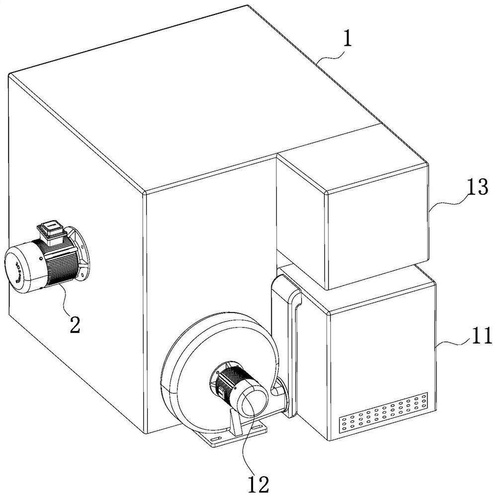
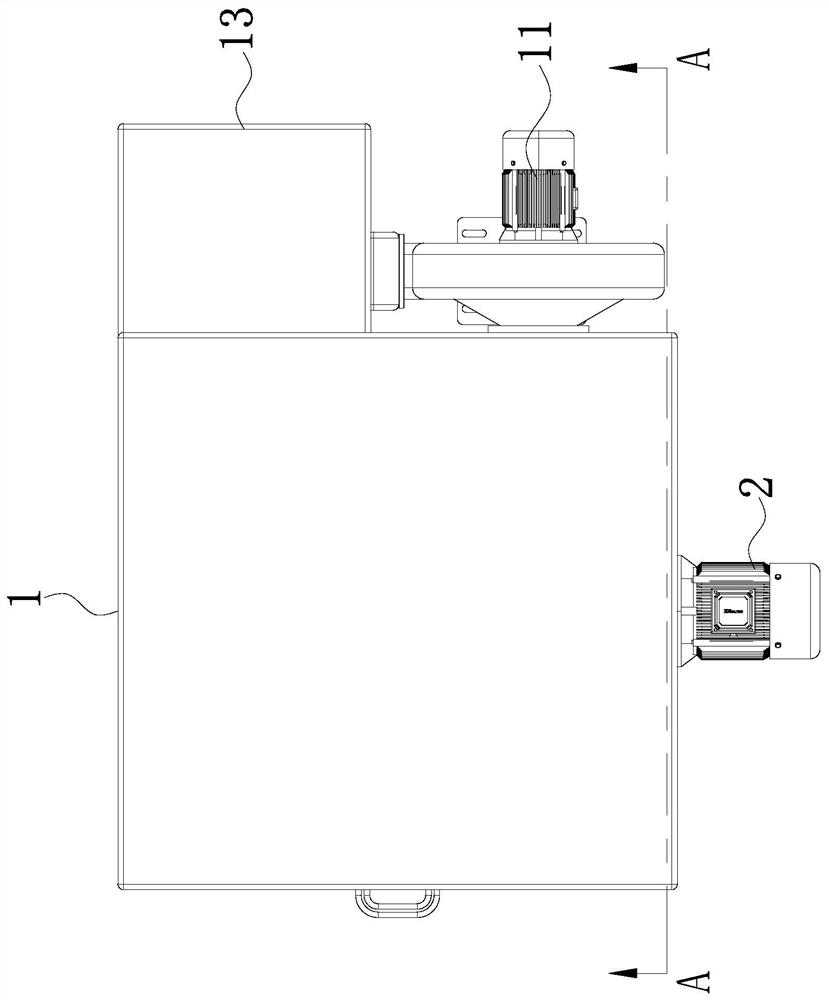
The invention belongs to the technical field of fertilizer coating production, and particularly relates to a fertilizer coating process, a coating machine used in the fertilizer coating process comprises a machine shell, a rotating motor and a fixed pipe; a working cavity is formed in the machine shell; a fixed pipe is fixedly connected to the interior of the working cavity; the front end face ofthe machine shell is fixedly connected with a rotating motor; a fertilizer box is fixedly connected to the position, close to the rear end face of the shell, of the right side face of the shell. According to the fertilizer coating device, rapid coating of the surfaces of fertilizer particles is effectively realized, a fertilizer layer is uniformly sprayed on the surface of the coating adhesive plate, then a coating solution is sprayed, and the problems of extrusion collision and stacking between the fertilizer particles are avoided, so that the coating thickness of the surfaces of the fertilizer particles is relatively uniform. If the coating thickness needs to be controlled, repeated coating can be carried out for multiple times, so that the coating thickness is effectively controlled, and the quality stability of the coated fertilizer is improved.

Description

technical field [0001] The invention belongs to the technical field of fertilizer coating production, in particular to a fertilizer coating process. Background technique [0002] Coated fertilizers, also known as coated fertilizers and film fertilizers, are fertilizers made of semi-permeable or impermeable film substances that wrap quick-acting fertilizer particles. The purpose of the coating is to make the quick-acting nutrients inside the coated fertilizers It is released slowly to prolong the fertilizer effect, and the release rate depends on the type, thickness, particle size, fertilizer solubility, soil temperature, soil moisture content and soil microbial activity of the coating, and the thickness of the coating is the coating fertilizer One of the key points of prolonging the fertilizer effect is that different crops have different requirements for the fertilizer effect time. In order to make the fertilizer effectively adapt to different crops and make full use of the...

Claims


Application Information

Patent Timeline
Patent Type & Authority Applications(China)
IPC IPC(8): C05G3/00C05G3/80C05G5/12C05G5/30
CPCC05B1/02C05G3/00C05G3/80C05G5/12C05G5/30C05B7/00C05C3/00C05C5/02C05C9/00C05D1/02C05D5/00C05D9/02C05F11/02
Inventor 孙仁贵王德平
Owner 当涂县江心仁贵家庭农场
Learn More