Adjustable formwork system for small-size deformation joint construction

A technology of formwork system and deformation joints, which is applied in the direction of formwork/formwork/work frame, connectors of formwork/formwork/work frame, and preparation of building components on site, which can solve the problem of inability to accurately ensure the size and Problems such as verticality, potential safety hazards, and long construction preparation time can avoid the difficulty of upper and lower safety protection and dynamic management, improve safety and reliability, and shorten the preparation and formwork time.

Pending Publication Date: 2021-02-26
CCFED THE FIGTH CONSTR & ENG
View PDF0 Cites 3 Cited by
  • Summary
  • Abstract
  • Description
  • Claims
  • Application Information

AI Technical Summary

Problems solved by technology

Therefore, the width of deformation joints for buildings with small heights is generally only 100-200 mm, while high-rise and small high-rise buildings are generally only 200-500 mm. Due to the small clearance distance of deformation joints, it is relatively difficult to install and remove formwork on both sides of deformation joints. Difficult, especially for small deformation joints of 100-200mm
[0003] For the formwork construction of small-sized deformation joints, the following three processes are often used in the prior art: the first is to use polystyrene boards as a one-time formwork, but due to the low strength of polystyrene boards, the expansion joints after concrete pouring and ramming Die expansion and mold explosion are prone to occur on the inner side, and the structural size and verticality of the concrete section cannot be guaranteed, and the cost of rework and rectification is relatively high
The second is to use wood plywood and wooden squares to make a box as large as the deformation joint as a template, or to make a grid support from plate-shaped strips as a template, but due to the extrusion of the construction load on both sides, It is difficult to dismantle, and if it is not dismantled, the rigid structure will directly affect the structural function of the deformation joint
The third is to adopt the staggered-layer construction method on both sides of the deformation joints, but there are also deformation joints that cannot be poured at the same time, the construction period is longer, and it also increases the difficulty of safety protection and dynamic management of the upper and lower operation floors
For this reason, in the prior art, holes are also opened in the formwork of the deformation joint, and then a wall-through screw rod that passes through the embedded sleeve in the wall is inserted, and the formwork on the outside is fixed from the inner side of the wall column, thereby solving the problem of small size. The wall columns on both sides of the deformation joint cannot be poured at the same time, or polystyrene boards need to be filled between the deformation joints, and wooden boxes are set as templates.
However, it should also be noted that the above-mentioned method needs to pre-embed the casing in the wall column structure, which will not only reduce the structural strength of the wall column, resulting in a decrease in waterproof performance, but also need to tighten the wall-penetrating screws one by one. The difference in the formwork will reduce the flatness of the formwork, and the structural size and verticality of the concrete section cannot be accurately guaranteed. After the deformation joint size is adjusted, it needs to be overturned and redone. When it is reused, the wall-through screw is a customized one-time product, and it is difficult to adapt flexibly. Deformation joints of different widths, resulting in relatively high cost of use and long construction preparation time
In addition, there is also a plan to use high-pressure airbags to inflate the formwork on both sides to support the formwork on both sides. When the formwork is removed, the formwork is depressurized for removal. Although it can be reused, it also solves the adverse effects of construction residues in the deformation joints. The support strength of the airbag after inflation is still limited, and it is difficult to avoid the problems of mold expansion and mold explosion after the concrete pouring and tamping is completed
In addition, elliptical steel pipes are used as components, and the support rods in the rotating top form removal device at the end of the elliptical steel pipes are used to open and close to adjust the distance between the formwork, so as to achieve the purpose of efficient assembly, disassembly and reuse, but there is also a single support rod The parts are easy to lose stability under strong construction loads, and only through the small upper part of the threaded connection to stabilize the size will cause excessive stress and pose a safety hazard, and for deformation joints of different sizes, corresponding elliptical steel pipes need to be made, and there is no universal type And cause the waste of materials, the use cost is higher

Method used


Image

  • Adjustable formwork system for small-size deformation joint construction
  • Adjustable formwork system for small-size deformation joint construction
  • Adjustable formwork system for small-size deformation joint construction

Examples


Embodiment Construction

[0021] The present invention will be further described below in conjunction with the accompanying drawings and examples, but the present invention is not limited in any way. Any changes or improvements made based on the teaching of the present invention belong to the protection scope of the present invention.

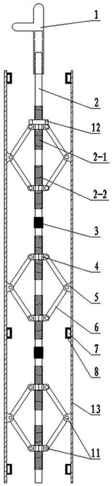
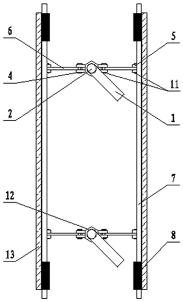
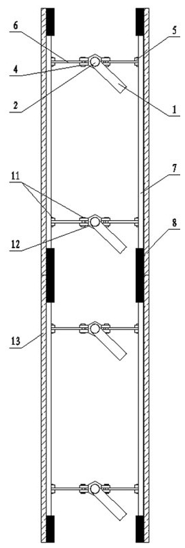
[0022] Such as figure 1 , 2 As shown in and 3, the present invention includes a handle 1, a screw rod 2, a connecting sleeve 3, a screw nut 4, an ear plate 5, a pull plate 6, and a steel formwork 13, and the screw rod 2 is provided with forward-rotating thread segments 2 at intervals along the axial direction. -1 and anti-rotation thread section 2-2, the connecting sleeve 3 is fixedly connected with the upper and lower adjacent screw rods 2, the handle 1 is arranged on the top of the top screw rod 2, and the screw nuts 4 are respectively arranged on the same screw rod 2 Corresponding threaded holes are provided on the forward-rotating threaded section 2-1 and the rever...


PUM


Abstract

The invention discloses a small-size deformation joint construction adjustable formwork system which is characterized in that forward thread sections and reverse thread sections are arranged on screwsat intervals in the axial direction, connecting sleeves are fixed to the vertically adjacent screws, and handles are arranged at the tops of the screws at the top ends. The nuts are respectively arranged on the forward thread section and the reverse thread section of the same screw and internally provided with corresponding threaded holes, the steel formworks are parallelly arranged on two sidesof the screw respectively, the lug plates are fixed on the steel formworks at intervals along the axial direction of the screw, and the nuts are hinged with one ends of the two pull plates on two sides corresponding to the steel formworks respectively. The other ends of the two pull plates hinged with the screw on the adjacent forward-rotating or reverse-rotating thread section of the screw rod are respectively hinged with the lug plates. The forward and reverse thread sections are arranged on the screw rods, so that the nuts, the lug plates and the pull plates form an openable shear type structure, the distance between the steel formworks can be conveniently adjusted, the problem that the formworks are difficult to mount and dismount in small-size deformation joint construction is solved,and the device has the advantages of being convenient to mount and dismount, flexible in adjustment, high in supporting strength and capable of being repeatedly used.

Description

technical field [0001] The invention belongs to the technical field of construction machinery, and in particular relates to an adjustable formwork system for construction of small-sized deformation joints which is convenient for disassembly and assembly, flexible in adjustment, high in support strength and reusable. Background technique [0002] In industrial and civil buildings, due to the influence of factors such as temperature changes, uneven foundation settlement and earthquakes, additional stress and deformation will be generated inside the building structure, especially small high-rise and high-rise buildings will amplify these additional stress and deformation, such as Improper handling can cause cracks or even collapse of the building structure. For this reason, it is necessary to disconnect the structure in the sensitive parts that may be deformed in advance to form deformation joints, so as to ensure that each part of the building structure has sufficient deformat...

Claims


Application Information

Patent Timeline
Patent Type & Authority Applications(China)
IPC IPC(8): E04G11/08E04G17/00E04G17/065
CPCE04G11/08E04G17/00E04G17/0657
Inventor 马龙蒋怡陆启宏杨艳蔡金新范凌云
Owner CCFED THE FIGTH CONSTR & ENG
Why Eureka
Try Eureka