
Method for charging by using new energy vehicle bus stop board

A technology for new energy vehicles and bus stop signs, which is applied in the field of using new energy vehicle bus stop signs for charging, can solve problems such as insufficient power and insufficient power, and achieve the effects of improving utilization, improving practicability, and being easy to use.

Inactive Publication Date: 2021-02-26
李梦林
View PDF11 Cites 2 Cited by
  • Summary
  • Abstract
  • Description
  • Claims
  • Application Information

AI Technical Summary

Problems solved by technology

[0006] Aiming at the deficiencies of the prior art, the present invention provides a method for charging by using the bus stop sign of a new energy vehicle, which has the advantages of being convenient for charging on the way of the bus, making full use of the utilization rate of the bus stop sign and having the function of convenience, etc., and solves the problem of In order to drive the bus to the terminal for recharging before use, however, the existing new energy buses will have insufficient power during use, due to the problem caused by insufficient power.

Method used


Image

  • Method for charging by using new energy vehicle bus stop board
  • Method for charging by using new energy vehicle bus stop board
  • Method for charging by using new energy vehicle bus stop board

Examples


Embodiment Construction

[0030] The following will clearly and completely describe the technical solutions in the embodiments of the present invention with reference to the accompanying drawings in the embodiments of the present invention. Obviously, the described embodiments are only some, not all, embodiments of the present invention. Based on the embodiments of the present invention, all other embodiments obtained by persons of ordinary skill in the art without making creative efforts belong to the protection scope of the present invention.

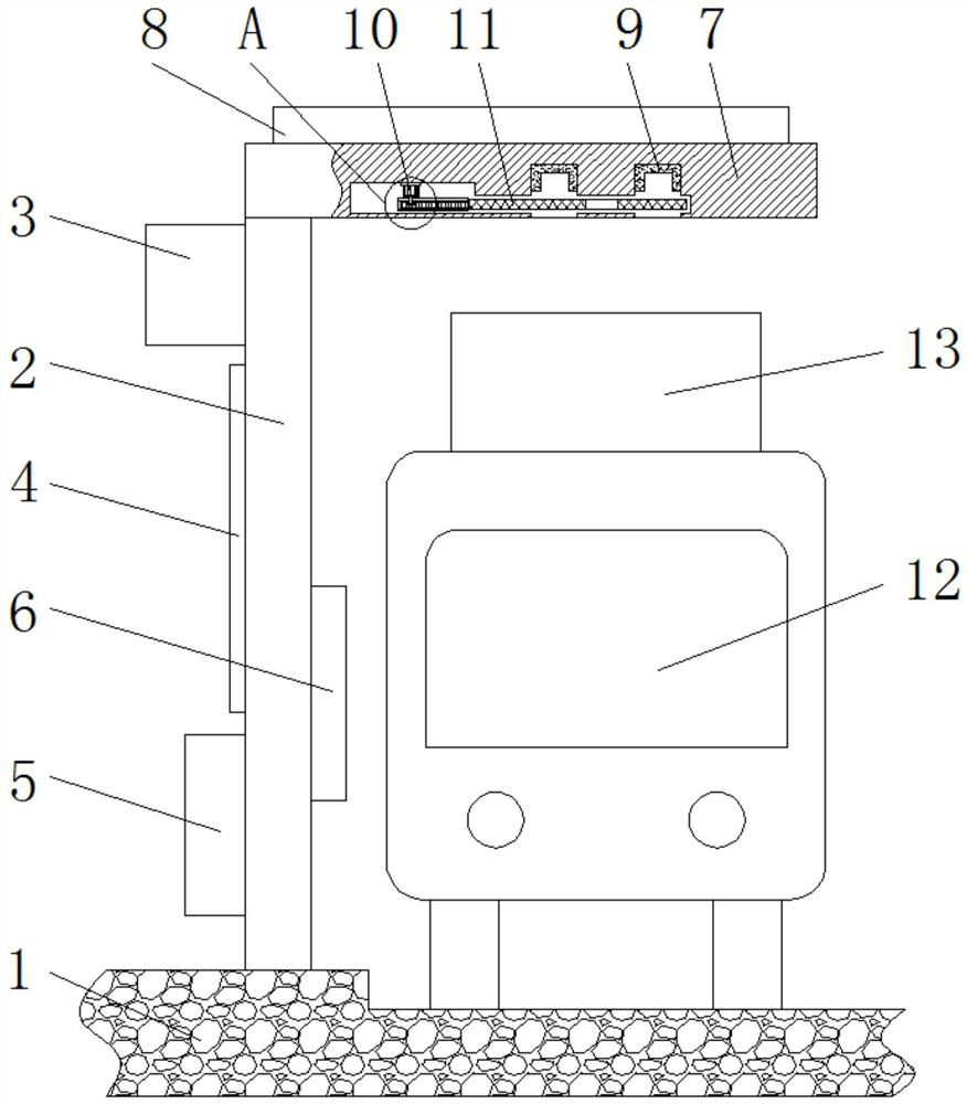
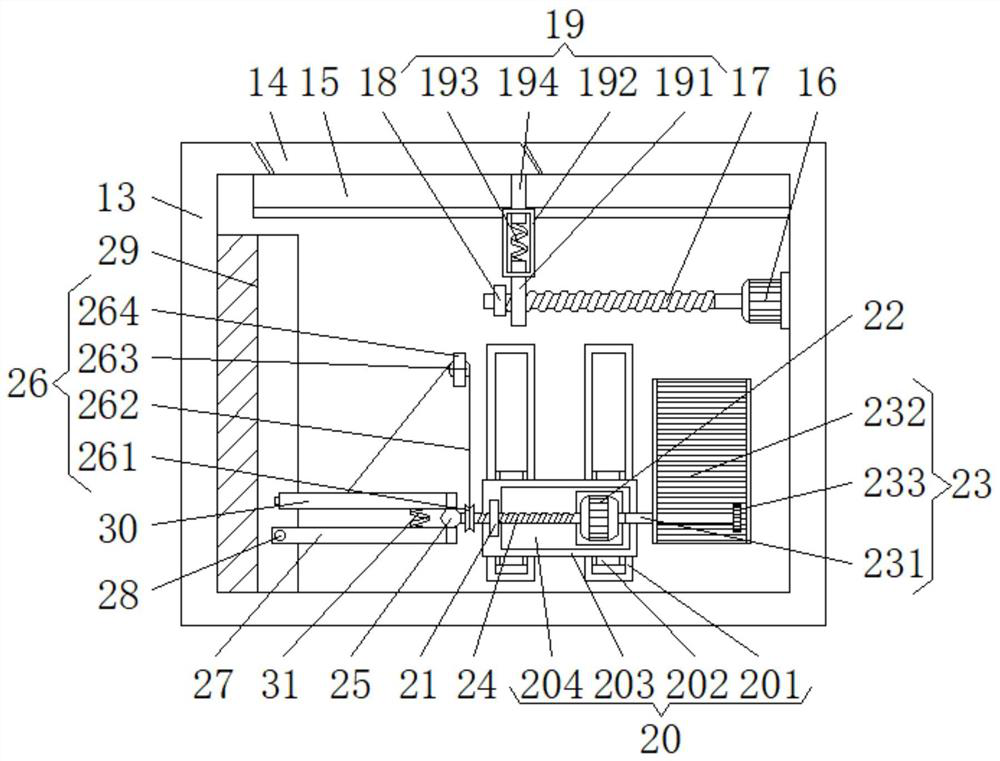
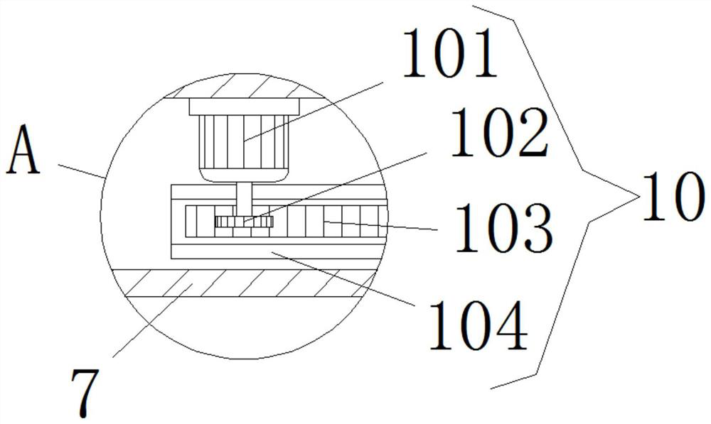
[0031] see Figure 1-6, the present invention provides a technical solution, a method for charging by using a new energy vehicle bus stop sign, including a bottom plate 1, a display board 2 is fixedly installed on one side of the top of the bottom plate 1, and one side of the display board 2 is from top to bottom A storage battery 3, a display screen 4 and a convenient charging box 5 are fixedly installed in sequence, a marking board 6 is fixedly installed on ...


PUM


Abstract

The invention relates to the technical field of new energy vehicles, and discloses a method for charging by using a new energy vehicle bus stop board. The bus stop board comprises a bottom board; a display board is fixedly mounted at one side of the top of the bottom board; a storage battery, a display screen and a convenient charging box are fixedly mounted at one side of the display board in sequence from top to bottom; a marking plate is fixedly installed on the front face of the bottom of the other side of the display plate; a top plate is fixedly installed at the top of the display plate;and a solar panel is fixedly installed at the top of the top plate. According to the method for charging by using the new energy vehicle bus stop board, the solar panel is installed on the top plate,a clamping groove plate is installed in the top plate, the opening and the closing of the clamping groove plate are controlled by a push and pull device and a sealing plate, and the marking plate isinstalled on the display plate so that a bus can be conveniently stopped at a proper position; and a box body is installed on the top of the bus, an upper guide rod and a lower guide rod are arrangedinside the box body, and the upper guide rod is in contact with the clamping groove plate, so that the bus stop board can be conveniently charged in the traveling process, and the function of chargingthe bus stop board of a new energy vehicle is realized.

Description

[0001] This application is a divisional application of a patent with an application date of May 7, 2018, an application number of 2018104255489, and an invention title of "A New Energy Vehicle Bus Stop". technical field [0002] The invention relates to the technical field of new energy vehicles, in particular to a charging method using a new energy vehicle bus stop. Background technique [0003] New energy vehicles refer to the use of unconventional vehicle fuels as power sources or the use of conventional vehicle fuels to adopt new vehicle power devices, comprehensive vehicle power control and advanced technology in driving, and the formation of advanced technical principles, new technologies, New structure vehicles, new energy vehicles include pure electric vehicles, extended-range electric vehicles, hybrid vehicles, fuel cell electric vehicles, hydrogen engine vehicles and other new energy vehicles. [0004] Existing new energy sources have been applied to various types ...

Claims


Application Information

Patent Timeline
Patent Type & Authority Applications(China)
IPC IPC(8): E04H1/12E04D13/18H02J7/35G09F9/00G09F15/00B60L53/14B60L53/51
CPCB60L53/14B60L53/51E04H1/1211E04H1/1233G09F9/00G09F15/00H02J7/35Y02T10/70Y02T10/7072Y02T90/12Y02T90/14
Inventor 段玉珍
Owner 李梦林
Learn More