
Industrial steam turbine nozzle chamber without halving surface

A technology for industrial steam turbines and nozzle chambers, applied in mechanical equipment, engine components, machines/engines, etc., can solve the problems of increased opening force, high cost, and increased cylinder design cost, and achieve reduced lateral size, simple structure, and reduced Effects of Manufacturing and Processing Costs

Active Publication Date: 2021-02-26
DONGFANG TURBINE CO LTD
View PDF10 Cites 0 Cited by
  • Summary
  • Abstract
  • Description
  • Claims
  • Application Information

AI Technical Summary

Problems solved by technology

First of all, due to the setting of the split bolt, the lateral dimension of the nozzle chamber is relatively large. For the steam turbine cylinder enveloping the steam chamber, the transverse dimension must be increased accordingly to ensure that the split bolt in the nozzle chamber does not contact the inner wall of the cylinder. For the cylinder, when the internal pressure is constant, the increase of the lateral dimension means that the "opening force" of the upper and lower halves increases, which increases the working stress of the mid-section bolts. Under the same conditions, the mid-section of the cylinder The design of the bolt needs to increase the specification, which increases the design cost of the cylinder
Secondly, due to the existence of facets in the nozzle chamber, due to the complex working state of the nozzle chamber itself, it is difficult to design flanges and bolts in order to ensure the sealing of the middle facet, and it also increases the cost of bolts and the processing cost of corresponding screw holes
Thirdly, in order to ensure that there is no steam leakage in the middle part of the nozzle chamber, the upper and lower half of the communication part is also equipped with a sealing ring structure. The processing of the middle part sealing ring structure is more complicated, the cost is high, the installation is more troublesome, and a special assembly process is required. , increasing the cost of the nozzle chamber

Method used


Image

  • Industrial steam turbine nozzle chamber without halving surface
  • Industrial steam turbine nozzle chamber without halving surface
  • Industrial steam turbine nozzle chamber without halving surface

Examples


Embodiment Construction

[0024] Embodiments of the present invention are described in detail below, examples of which are shown in the drawings, wherein the same or similar reference numerals designate the same or similar elements or elements having the same or similar functions throughout. The embodiments described below by referring to the figures are exemplary and are intended to explain the present invention and should not be construed as limiting the present invention.

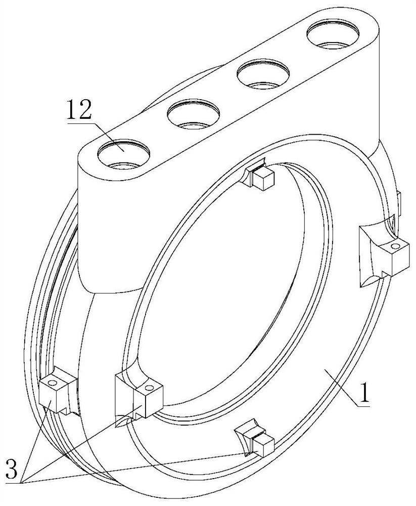
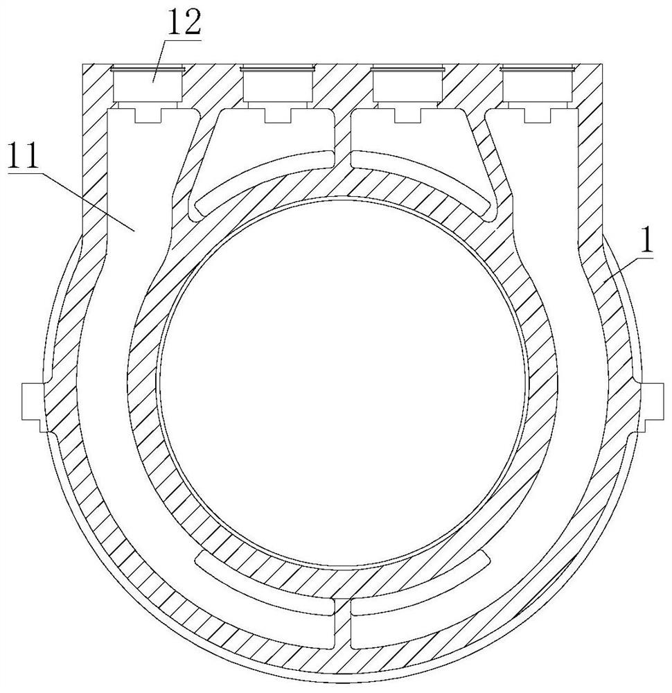
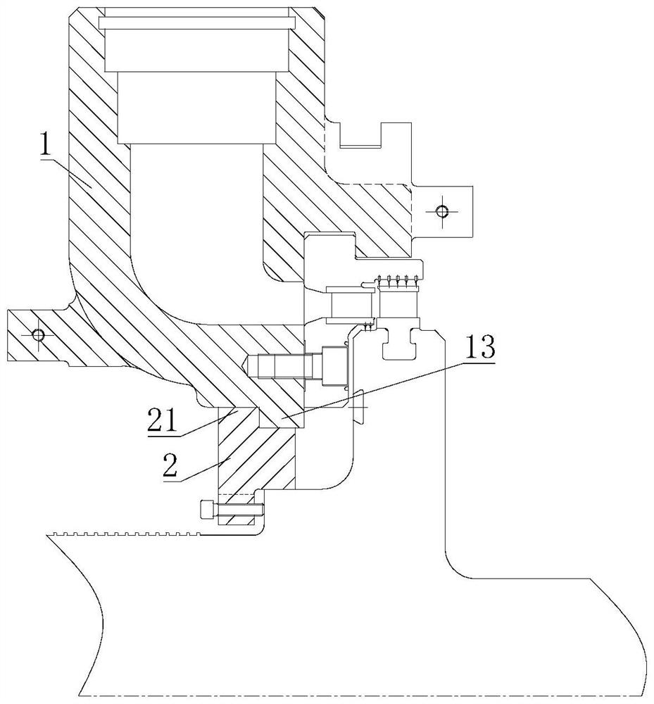
[0025] Such as Figure 1 to Figure 4 As shown, the nozzle chamber of an industrial steam turbine without mid-section in this embodiment includes an integral nozzle chamber main body 1, and several steam chambers 11 are arranged in the nozzle chamber main body 1, and the steam chamber 11 is connected with a regulating valve seat installed Hole 12, the regulating valve seat installation hole 12 is set on the nozzle chamber main body 1; the inner side of the nozzle chamber main body 1 is provided with a lifting accessory 2 for lifti...


PUM


Abstract

The invention belongs to the technical field of industrial steam turbines, and particularly relates to an industrial steam turbine nozzle chamber without a halving surface. According to the technicalscheme, the industrial steam turbine nozzle chamber without the halving face comprises an integrated nozzle chamber body, wherein a plurality of steam cavities are formed in the nozzle chamber body, the steam cavities communicate with adjusting valve seat mounting holes which are formed in the nozzle chamber body; a hoisting accessory used for supporting the nozzle chamber body is arranged on theinner side of the nozzle chamber body and arranged on a rotor of a steam turbine in a sleeving mode. According to the industrial steam turbine nozzle chamber without the halving face, the problems that the halving face leaks air, and the transverse size of the nozzle chamber and an outer cylinder is large are solved.

Description

technical field [0001] The invention belongs to the technical field of industrial steam turbines, and in particular relates to a nozzle chamber of an industrial steam turbine without a center facet. Background technique [0002] For industrial steam turbines, a large number of unit steam distribution methods use nozzle steam distribution, and the key part to realize nozzle steam distribution is the steam turbine nozzle group, which is the stator blade part of the regulating stage. The structure where the nozzle group is installed is called the nozzle chamber. The nozzle chamber is essentially a pressure-bearing cylinder. Steam enters the nozzle set. The nozzle chamber of the steam turbine is a key part inside the steam turbine. It works in the steam inlet section of the steam turbine. The temperature and pressure are relatively high, which puts forward higher requirements for its strength. [0003] Such as Figure 4 and Figure 5 As shown, in order to facilitate the assem...

Claims


Application Information

Patent Timeline
IPC IPC(8): F01D9/04F01D17/14
CPCF01D9/047F01D17/145
Inventor 钟波尹华劼尹刚范小平张勇邓凡龚露戴宇龙孙浩云熊春杨恒熠侯为中吴凯豪
Owner DONGFANG TURBINE CO LTD
Features
  • Generate Ideas
  • Intellectual Property
  • Life Sciences
  • Materials
  • Tech Scout
  • Unparalleled Data Quality
  • Higher Quality Content
  • 60% Fewer Hallucinations
Learn More