Compressed air energy storage system and thermal power plant control system coupling control method

A technology for compressed air energy storage and thermal power plants, which is applied to machines/engines, steam engines, mechanical equipment, etc. It can solve the problems of heat loss of heat storage equipment, large heat release from compression heat, etc., so as to improve utilization and reduce heat consumption. , the effect of increasing market competitiveness

Active Publication Date: 2021-02-26
GUIZHOU POWER GRID CO LTD
View PDF13 Cites 4 Cited by
  • Summary
  • Abstract
  • Description
  • Claims
  • Application Information

AI Technical Summary

Problems solved by technology

[0003] The technical problem to be solved by the present invention is to provide a coupling control method between the compressed air energy storage system and the thermal power plant control system, so as to solve the problem that the compressed air energy storage system in the prior art releases to the heat storage worker during the charging and discharging process. The amount of heat released by the compression heat of the substance is greater than the heat absorbed by the heat storage medium released to the air during the discharge process, resulting in technical problems such as heat loss of the heat storage equipment

Method used


Image

  • Compressed air energy storage system and thermal power plant control system coupling control method
  • Compressed air energy storage system and thermal power plant control system coupling control method

Examples


Embodiment Construction

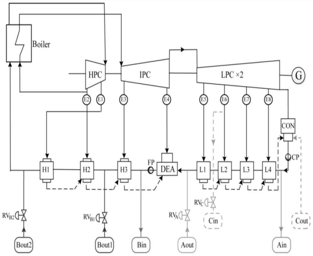
[0025] The coupling control of the present invention is composed of two main subsystems, namely a compressed air energy storage system and a thermal power generation system. Such as figure 1 As shown, a typical thermal power generation system consists of a boiler, a high-pressure cylinder HP, a medium-pressure cylinder IP and two low-pressure cylinders LP. The regeneration system includes eight steam turbine extractions E1-E8, corresponding to three high-pressure recuperation heaters H1-H3, four low-pressure recuperation heaters L1-L4 and a deaerator DEA.

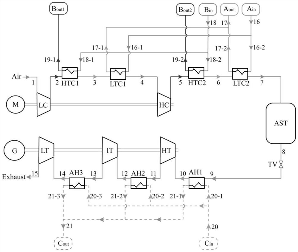
[0026] Such as figure 2 The shown compressed air energy storage system consists of charging and discharging two parts. The charging process includes a motor M, a two-stage compressor unit LC and HC, two high-temperature air coolers HTC1, HTC2, two low-temperature air coolers LTC1, LTC2 and an air storage tank AST. During charging, ambient air is compressed and stored in the air storage tank AST. The compressor outlet a...


PUM


Abstract

The invention discloses a compressed air energy storage system and thermal power plant control system coupling control method. The compressed air energy storage system and thermal power plant controlsystem coupling control method comprises compressed air energy storage system charging process control and discharging process control, and during the charging process control, ambient air is compressed and stored in an air storage tank AST; outlet air of a compressor is cooled by air coolers; outlet water of a condensation pump is fed into a low-temperature air cooler LTC1 and a low-temperature air cooler LTC2 and heated to the outlet temperature of a regenerative heater L1 of a control system of a thermal power plant; and outlet water of a water feeding pump is supplied to a high-temperatureair cooler HTC1 and a high-temperature air cooler HTC2 of a compressed air energy storage system so as to be merged into an outlet of the corresponding regenerative heater of a thermal power generation system. The technical problem that in the charging and discharging process of the compressed air energy storage system in the prior art, the heat loss of heat storage equipment is caused due to thefact that the compressed heat release amount released to a heat storage working medium in the charging process is larger than the heat absorption amount released to air by the heat storage working medium in the discharging process is solved.

Description

technical field [0001] The invention belongs to the technical field of energy storage, and in particular relates to a coupling control method of a compressed air energy storage system and a thermal power plant control system. Background technique [0002] The compressed air energy storage system uses a compressor to pressurize the air to a higher pressure during the low electricity consumption, and then cools and stores it in the air storage tank to consume electric energy. The air expander generates electricity to provide electricity to the grid. Compared with other energy storage technologies, the compressed air energy storage system has the characteristics of large unit capacity, low investment per unit power, and long design life, and has great development potential. At present, the compressed air energy storage unit in industrial operation belongs to the non-adiabatic compressed air energy storage system. During the discharge process of the system, the fuel needs to be...

Claims


Application Information

Patent Timeline
Patent Type & Authority Applications(China)
IPC IPC(8): F01K27/00F01K13/02F01K13/00
CPCF01K27/00F01K13/02F01K13/00Y02E60/16
Inventor 文贤馗钟晶亮邓彤天张世海王文强王锁斌李翔吴鹏李前敏席光辉田今朝熊浩然
Owner GUIZHOU POWER GRID CO LTD
Why Eureka
Try Eureka