Cavitation-preventing device for condensate pump

A technology for anti-cavitation and water pumps, which is applied to components, pumps, and pump components of elastic fluid pumping devices, and can solve problems such as damage to impellers, high civil construction costs, and limited transformation capabilities of circulating water systems. Reduce the inlet water temperature, improve cavitation conditions, effective and reliable cavitation conditions

Pending Publication Date: 2021-02-26
彭佳丽
View PDF7 Cites 1 Cited by
  • Summary
  • Abstract
  • Description
  • Claims
  • Application Information

AI Technical Summary

Problems solved by technology

[0002] In power plants, whether it is thermal power or nuclear power, steam is used to drive steam turbines to generate electricity, and the steam that has passed through steam turbines turns into low-pressure, low-temperature steam, and after condensation, it becomes condensed water, although it is called condensation in name However, its actual temperature is still higher than that of ordinary liquid water. If this high-temperature and low-pressure liquid water is directly sent into the pump for pumping, it is easy to cause cavitation, that is, the water body is vaporized at the inlet of the pump and then Bubbles burst after slight pressurization and damage the impeller
[0003] In the prior art, the cavitation performance is usually improved by reducing the installation height of the condensate pump. It is common for the condensate pump to be installed below the ground and surrounded by a metal cylinder, which is similar to a cylindrical cylinder, so it is also called "barrel bag pump". ", this method of improving cavitation performance is very costly in civil engineering, and the condensate pump is less economical when the flow rate is small, and it is impossible to move and change the pipeline at all, so the transformation capacity of the circulating water system is greatly limited

Method used


Image

  • Cavitation-preventing device for condensate pump
  • Cavitation-preventing device for condensate pump
  • Cavitation-preventing device for condensate pump

Examples


specific Embodiment approach 1

[0025] see Figure 1-3 ,

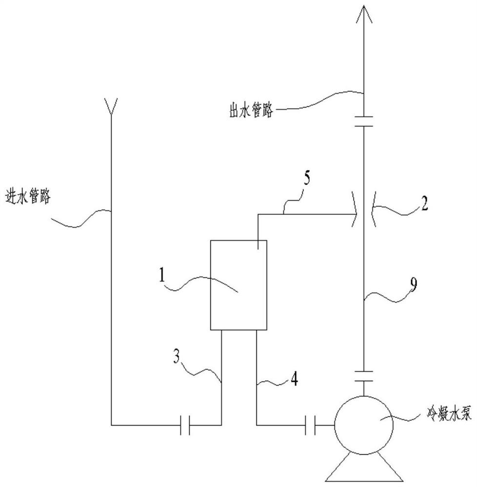
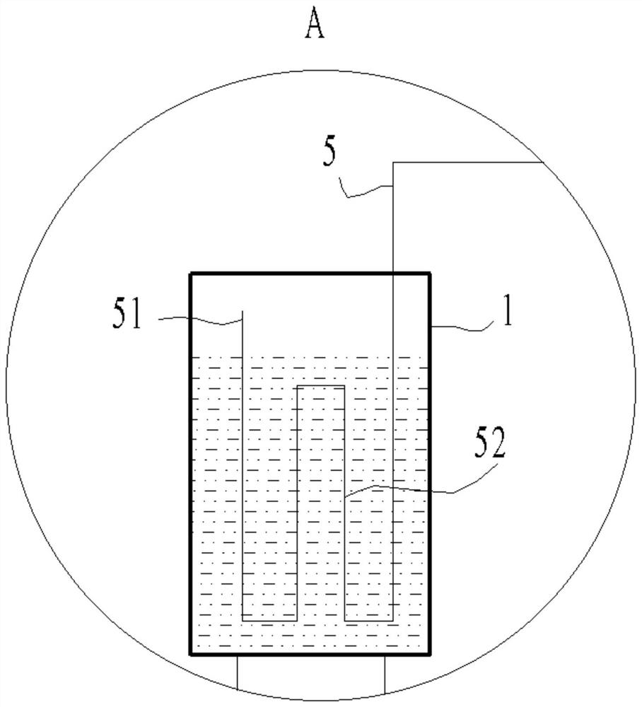
[0026] The anti-cavitation device of the condensate pump is installed between the condensate pump, the water inlet pipeline and the water outlet pipeline. The outlet pipe 9, the gas-liquid separation assembly is connected to the water inlet pipe through the inlet pipe 3, the gas-liquid separation assembly is connected to the inlet of the condensate pump through the outlet pipe 4, and the pump outlet pipe 9 is connected to the outlet of the condensate pump and the outlet pipe, and the pump outlet pipe 9 is set The drainage component 2 and the gas-liquid separation component are connected to the drainage component 2 through the air outlet pipe 5, and the installation height of the gas-liquid separation component is higher than the water inlet of the condensate pump. The cavitation at the water inlet of the condensate pump is caused by the vaporization of water. The condition of vaporization is an increase in temperature or a decrease in pressure. Most...

specific Embodiment approach 2

[0033] The separation tank 1 in the specific embodiment one is replaced by a separation cylinder 6, for details see Figure 4~6 :

[0034] The gas-liquid separation component is a separation cylinder 6. The separation cylinder 6 includes a cylinder body 61, a spiral blade 62, and an air induction pipe 63. The top of the cylinder body 61 is connected to the inlet pipe 3, and the bottom of the cylinder body 61 is connected to the liquid outlet pipe 4. The upper part of the cylinder body 61 is A fixed helical blade 62 is provided, and the helical blade 62 directs the flow of the working medium flowing through it into a spiral descent. One end of the air-inducing pipe 63 is set inside the cylinder body 61, and the other end passes through the side wall of the cylinder body 61 and connects to the air outlet pipe 5 outward. The vertical part of the air pipe 63 inside the cylinder body 61 is coaxial with the cylinder body 61 , and the air induction pipe 63 is located below the helica...


PUM


Abstract

The invention discloses a cavitation-preventing device for a condensate pump. The cavitation-preventing device for the condensate pump is arranged among the condensate pump, a water inlet pipeline anda water outlet pipeline. The cavitation-preventing device comprises a gas-liquid separation assembly, a drainage assembly, an inlet pipe, a liquid outlet pipe, a gas outlet pipe and a pump-out pipe.The gas-liquid separation assembly is connected with the water inlet pipeline through the inlet pipe and connected with an inlet of the condensate pump through the liquid outlet pipe. The pump-out pipe is connected with an outlet of the condensate pump and the water outlet pipeline. The drainage assembly is arranged on the pump-out pipe. The gas-liquid separation assembly is connected with the drainage assembly through the gas outlet pipe. The installation height of the gas-liquid separation assembly is larger than that of a water inlet of the condensate pump. The drainage assembly comprises afirst jet device, a branch pipe and a second jet device. The first jet device and the second jet device are Venturi tubes. The first jet device is arranged on the pump-out pipe. One end of the branchpipe is connected to the portion, which is located in front of the first jet device, of the pump-out pipe, and the other end of the branch pipe is connected to the throat portion of the first jet device. The second jet device is arranged on the branch pipe. The throat portion of the second jet device is connected with the gas outlet pipe.

Description

technical field [0001] The invention relates to the technical field of condensed water pumps, in particular to a condensed water pump anti-cavitation device. Background technique [0002] In power plants, whether it is thermal power or nuclear power, steam is used to drive steam turbines to generate electricity, and the steam that has passed through steam turbines turns into low-pressure, low-temperature steam, and after condensation, it becomes condensed water, although it is called condensation in name However, its actual temperature is still higher than that of ordinary liquid water. If this high-temperature and low-pressure liquid water is directly sent into the pump for pumping, it is easy to cause cavitation, that is, the water body is vaporized at the inlet of the pump and then Bubbles burst after slight pressurization and damage the impeller. [0003] In the prior art, the cavitation performance is usually improved by reducing the installation height of the condensa...

Claims


Application Information

Patent Timeline
Patent Type & Authority Applications(China)
IPC IPC(8): F04D29/66F04D29/58
CPCF04D29/669F04D29/586
Inventor 彭佳丽
Owner 彭佳丽
Why Eureka
Try Eureka