Lifting device for electronic equipment

A technology for electronic equipment and lifting devices, applied in projection devices, mechanical equipment, instruments, etc., can solve the problems of limited ceiling hanging height, insufficient aesthetics, and inability to completely hide installation, etc., to improve aesthetics, good integrity and Aesthetics, easy to connect and install

Active Publication Date: 2021-04-30
江苏精研动力系统有限公司
View PDF10 Cites 0 Cited by
  • Summary
  • Abstract
  • Description
  • Claims
  • Application Information

AI Technical Summary

Problems solved by technology

[0003] For example, when installing a projector, if there is no ceiling at the installation location, the lifting device must be exposed. After the existing lifting device is installed and used, the overall aesthetics is not enough
If there is a ceiling at the installation location, but the hanging height of the ceiling is limited, there is a problem that the installation cannot be completely hidden

Method used


Image

  • Lifting device for electronic equipment
  • Lifting device for electronic equipment
  • Lifting device for electronic equipment

Examples


Embodiment Construction

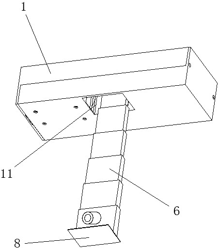
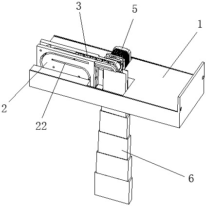
[0044] See figure 1 with figure 2 , the present invention includes a mounting frame 1, a chain storehouse 2, a chain 3, a transmission gear 4, a driving motor 5 and a telescopic casing 6; the mounting frame 1 is a box body with a lid; the lower end surface of the box body is provided with an opening 11; The body is fixedly provided with a chain storehouse 2, a transmission gear 4 and a drive motor 5.

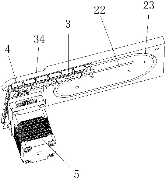
[0045] See Figure 4 to Figure 6 , with two symmetrically arranged chains 3, the chains 3 include a plurality of chains 31 and a plurality of bent chains 32; adjacent chains 31 are connected by a bent chain 32; two chains 3 pass through a rotating shaft 33 Simultaneous bending is formed after passing through the chain pieces 31 and the bending chain pieces 32 corresponding to the two chains 3 at the same time;

[0046] A wire cover plate 36 is provided on the bent chain piece 32 on one of the chains 3 ; a threading slot 35 is formed between the two chains 3 and between the c...


PUM


Abstract

The invention relates to a lifting device for electronic equipment, which includes a mounting frame, a chain warehouse, a chain, a transmission gear and a driving motor; the chain includes a plurality of chain pieces and a plurality of bent chain pieces; adjacent chain pieces are connected by a bent chain piece, And the chain piece and the bent chain piece form a rotational connection through the rotating shaft; the driving motor is fixedly installed on the mounting frame, and the output shaft of the driving motor is connected to the transmission gear; the side of the chain corresponding to the transmission gear is arranged along its sliding direction. A driving body; the chain warehouse is fixedly installed on the mounting frame, and the chain warehouse is provided with a storage chamber for the chain to slide out or slide in when the driving body is moved by the transmission gear; one end of the chain is always located in the storage chamber. , the other end of the chain protrudes from the storage compartment and forms a connecting end; the end of the chain protruding from the storage compartment is vertically downward by gravity. The invention has an ingenious structural design, can achieve a longer lifting stroke in a limited space, and the lifting is stable and reliable, and can effectively reduce the problem of lifting and shaking.

Description

technical field [0001] The invention relates to a device for driving lifting, in particular to a lifting device for electronic equipment. Background technique [0002] Lifting devices are widely used in many fields, such as the lifting of projectors, the lifting of televisions, and other electronic devices that need to achieve lifting requirements. Existing lifting devices generally include electric telescopic rods (or lifting mechanisms based on the principle of electric telescopic rods), connecting rod lifting mechanisms, etc. These lifting devices have a relatively large overall structure in order to ensure the lifting stroke. If the installation space in the vertical direction is limited, then the existing lifting device often brings a lot of troubles during installation. [0003] For example, when installing a projector, if there is no ceiling at the installation location, the lifting device must be exposed. After the existing lifting device is installed and used, the ...

Claims


Application Information

Patent Timeline
Patent Type & Authority Patents(China)
IPC IPC(8): G03B21/54F16M11/28F16M11/04F16G13/20
CPCF16M11/046F16M11/28G03B21/54
Inventor 唐石桥沈征飞张军伟朱卫东
Owner 江苏精研动力系统有限公司
Why Eureka
Try Eureka