
Novel double-source heat pump system utilizing phase-change energy storage technology

A phase-change energy storage, dual-source heat pump technology, applied in heating systems, heat pumps, household heating, etc., can solve the problems of uneconomical use of air, insufficient heat supply by heat pumps, and restrictions on promotion, to achieve continuous heat supply, improve The effect of heat supply stability

Inactive Publication Date: 2021-02-26
SHENYANG JIANZHU UNIVERSITY
View PDF9 Cites 0 Cited by
  • Summary
  • Abstract
  • Description
  • Claims
  • Application Information

AI Technical Summary

Problems solved by technology

However, due to the limitation of climatic conditions, the promotion of air source and ground source heat pumps in severe cold and cold areas is greatly restricted.
[0003] At present, the traditional dual-source heat pump system, in the heating mode, adopts the air source heat pump for heating, which is affected by the temperature difference between day and night. There is a phenomenon that the heat pump provides excess heat during the day and insufficient heat supply at night when the outside temperature drops, and cannot fully utilize the ultra-low temperature. Advantages of air energy heat pump heating. If the ambient temperature is too low and the heating load is high, it is uneconomical to use air energy. At this time, it is necessary to start the soil source as the heat source

Method used


Image

  • Novel double-source heat pump system utilizing phase-change energy storage technology
  • Novel double-source heat pump system utilizing phase-change energy storage technology
  • Novel double-source heat pump system utilizing phase-change energy storage technology

Examples


Embodiment Construction

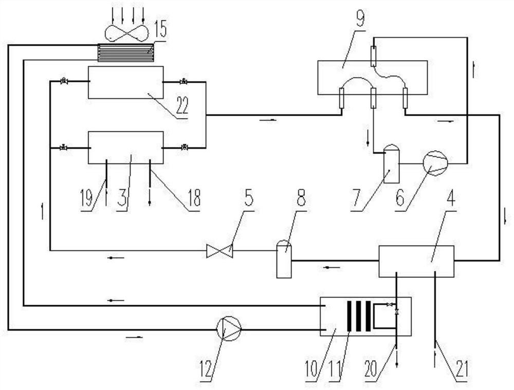
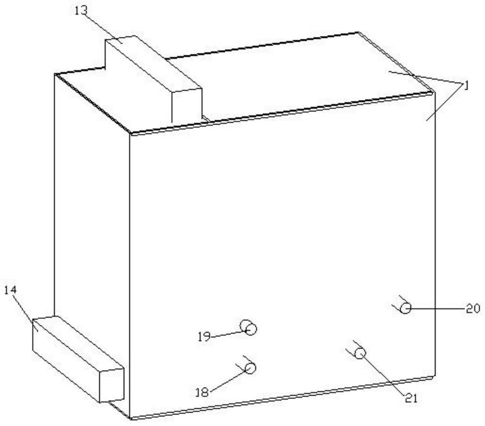
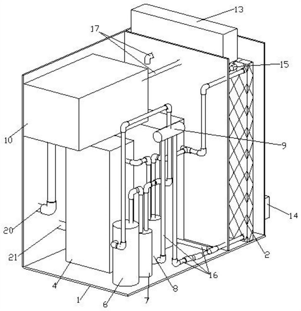
[0022] see Figure 1 to Figure 5 , a new dual-source heat pump system using phase change energy storage technology, including a unit casing 1 and a phase change energy storage water tank 10, characterized in that: the unit casing 1 is divided into a closed cavity on the air source side and a ground by a partition A closed cavity on the source side, a finned heat exchanger 2 is fixed in the closed cavity on the air source side, a ground source side evaporator 3, a user side condenser 4, a throttle Valve 5, compressor 6, liquid storage device 7, liquid separator 8, four-way valve 9, phase change energy storage water tank 10, water pump 12, multiple groups of paraffin-encapsulated tubes 11 are fixed in the phase change energy storage water tank 10 , the paraffin wax packaging tube 11 is packaged with paraffin, the outlet of the compressor 6 is connected to the first inlet of the four-way valve 9 through the refrigerant pipeline 16, and the first outlet of the four-way valve 9 is ...


PUM


Abstract

The invention discloses a novel double-source heat pump system utilizing a phase-change energy storage technology. The double-source heat pump system is characterized in that a unit shell is divided into an air source side closed cavity and a ground source side closed cavity through a partition plate; a fin heat exchanger is fixed in the air source side closed cavity; multiple groups of paraffin packaging pipes are fixed in a phase-change energy storage water tank; an outlet of a compressor is connected with a first inlet of a four-way valve through a refrigerant pipeline; a first outlet of the four-way valve is connected with a refrigerant inlet of a user side condenser through a refrigerant pipeline; a refrigerant outlet of the user side condenser is connected with an inlet of a liquid distributor through a refrigerant pipeline; an outlet of the liquid distributor is connected with refrigerant inlets of an air source side evaporator and a ground source side evaporator through refrigerant pipelines; a throttling valve is installed on a refrigerant pipeline on the back part of the liquid distributor; and an outlet of a liquid storage device is connected with an inlet of a compressor through the refrigerant pipeline. The double-source heat pump system has the advantages of good stability, high efficiency and good continuity.

Description

technical field [0001] The invention belongs to the technical field of dual-source heat pumps, and in particular relates to a novel dual-source heat pump system utilizing phase change energy storage technology. Background technique [0002] In order to continuously improve the living environment of human beings and increase the utilization rate of renewable energy, China and the rest of the world are paying more and more attention to the research of renewable energy technology. As one of the energy-saving technologies, heat pumps have received widespread attention from all over the world. Among them, air source and soil source are the most widely used, because these two types of heat pumps are easy to use and produce no pollution. They are the inevitable trend of my country's future development. However, due to the limitation of climatic conditions, the promotion of air source and ground source heat pumps in severe cold and cold areas is greatly restricted. [0003] At pres...

Claims


Application Information

Patent Timeline
IPC IPC(8): F24D15/04F24D11/00F25B30/06F25B13/00F25B41/40F25B41/20F25B43/00F25B39/00
CPCF24D11/002F24D15/04F25B13/00F25B30/06F25B39/00F25B43/006
Inventor 冯国会张磊黄凯良李旭林常莎莎江明志
Owner SHENYANG JIANZHU UNIVERSITY
Learn More