Machine room air conditioning system control method and system

A computer room air conditioner and control method technology, applied in heating and ventilation control systems, heating and ventilation safety systems, refrigerators, etc. Increase system resistance, prevent refrigerant migration, and avoid low suction pressure

Inactive Publication Date: 2021-02-26
GREE ELECTRIC APPLIANCES INC
View PDF7 Cites 0 Cited by
  • Summary
  • Abstract
  • Description
  • Claims
  • Application Information

AI Technical Summary

Problems solved by technology

[0003] Because the ambient temperature range of the computer room air conditioner is wide, when the unit is shut down, the refrigerant will migrate with the change of the indoor and outdoor temperature difference, and the migration of the refrigerant will seriously affect the start-up performance and reliability.
The outdoor temperature is too low, and the refrigerant migrates to the outdoor side after shutdown, which will cause the pressure difference between high and low pressure to not be established when starting up, and the suction pressure of the compressor is too low, causing low pressure protection and failing to start up
When the outdoor temperature is too high, the refrigerant migrates to the indoor side after the shutdown, resulting in too much refrigerant in the evaporator, and it is easy to cause liquid in the suction when the startup is started
In order to limit the migration speed of the refrigerant, the expansion valve is usually closed immediately when the machine is shut down, which will lead to an unbalanced high and low pressure difference or a long balance time, which will cause the compressor to start under pressure when the machine is turned on, seriously affecting the service life of the compressor

Method used


Image

  • Machine room air conditioning system control method and system

Examples


Embodiment Construction

[0024] In order to make the purpose, technical solution and advantages of the present disclosure clearer, the technical solution of the present disclosure will be clearly and completely described below in conjunction with specific embodiments of the present disclosure and corresponding drawings. Apparently, the described embodiments are only some of the embodiments of the present disclosure, but not all of them. Based on the embodiments in the present disclosure, all other embodiments obtained by persons of ordinary skill in the art without making creative efforts belong to the protection scope of the present disclosure.

[0025] This embodiment provides a method for controlling an air-conditioning system in a computer room, including:

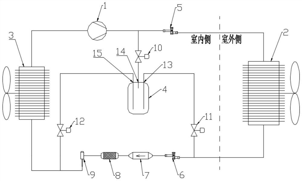
[0026] When shutting down when there is a temperature difference between indoor and outdoor, first close the electronic expansion valve 9 and open the second solenoid valve 11 at the same time, the expander 4 is connected to the high-pressure ...


PUM


Abstract

The invention provides a machine room air conditioning system control method. The method comprises the steps that when shutdown is conducted in the indoor and outdoor temperature difference state, anelectronic expansion valve is closed, and a refrigerant in a high-pressure side pipeline is guided to flow to an expander connected with a main circulation flow path in parallel; and the expander is disconnected until the condensation pressure in the main circulation flow path is reduced to be equal to the pressure in the expander. According to the control method, refrigerant migration caused by indoor and outdoor temperature difference during shutdown is effectively prevented, and the problems of low air suction pressure, low-pressure protection and the like of a compressor during restarting,the problem of air suction with liquid during starting of the compressor and the problem of under-pressure starting of the compressor due to imbalance of high pressure and low pressure or overlong balance time are avoided. Meanwhile, the expander is connected with the main circulation flow path in parallel, normal circulation of the refrigerant along the main circulation flow path is not affectedwhen a machine room air conditioner is normal, system resistance cannot be increased, and the refrigerating capacity and the energy efficiency ratio of a unit cannot be affected.

Description

technical field [0001] The disclosure belongs to the technical field of computer room air conditioners, and in particular relates to a control method and system for a computer room air conditioner system. Background technique [0002] With the rise of the communications industry and the advent of the era of artificial intelligence and 5G, the computing load of data center equipment is increasing, and its heat density has also increased significantly. As the cooling equipment of the data center, the air conditioner in the computer room is used in an ambient temperature between -40°C and 50°C due to different regions, which poses a severe test to the performance and reliability of the air conditioner in the computer room. [0003] Because the computer room air conditioner is used in a wide temperature range, when the unit is shut down, the refrigerant will migrate with the temperature difference between indoor and outdoor. The migration of refrigerant will seriously affect the...

Claims


Application Information

Patent Timeline
Patent Type & Authority Applications(China)
IPC IPC(8): F24F11/84F24F11/64F25B41/31F25B41/40F25B41/20F24F110/12
CPCF25B2500/28F25B2600/2513F24F11/64F24F11/84F24F2110/12
Inventor 王强荆莹任启峰黄玉优湛碧海林海佳
Owner GREE ELECTRIC APPLIANCES INC
Why Eureka
Try Eureka