Hydraulic push-back impact oscillator

An impact vibration and hydraulic technology, which is applied in the direction of vibration drilling, can solve the problems of high tool cost, long maintenance period, and limited tool application, so as to reduce the probability of drill sticking, stabilize the transmission of drilling pressure and improve the life of the drill bit. Effect

Active Publication Date: 2018-02-16
BAOJI YUANSHEN PETROLEUM EQUIP NEW TECH CO LTD
View PDF11 Cites 0 Cited by
  • Summary
  • Abstract
  • Description
  • Claims
  • Application Information

AI Technical Summary

Problems solved by technology

[0005] But at present, hydraulic oscillator tools generally use the screw motor to drive the disc valve to achieve pulse back pressure. The screw motor stator is a special spiral structure of rubber material, and the rotor is a specific spiral structure processed by a special CNC lathe and a special tool. , the cost of the tool is high, and the structure is more complicated
On the one hand, the manufacturing cost is high, and on the other hand, the maintenance of the tools after use is relatively difficult. Professional operators from the original factory are required to disassemble and maintain them in special workshops and special tools. The more common method is to send them back to the original factory for maintenance, resulting in Tool maintenance costs are also high and the maintenance cycle is long, which is not suitable for low-cost operations.
[0006] In addition, when the working fluid is a multiphase fluid such as foam, the screw motor must be equipped with a downhole gas separator to maximize the motor’s effectiveness. Application of Long Horizontal Section Horizontal Wells and Low Pressure Gas Reservoirs
[0007] When the downhole temperature is high or contains chemical substances that are corrosive to rubber, it will often cause the rubber stator of the screw motor to fail, resulting in a short service life

Method used


Image

  • Hydraulic push-back impact oscillator

Examples


Embodiment Construction

[0028] The present invention will be described in detail below in conjunction with the accompanying drawings and specific embodiments.

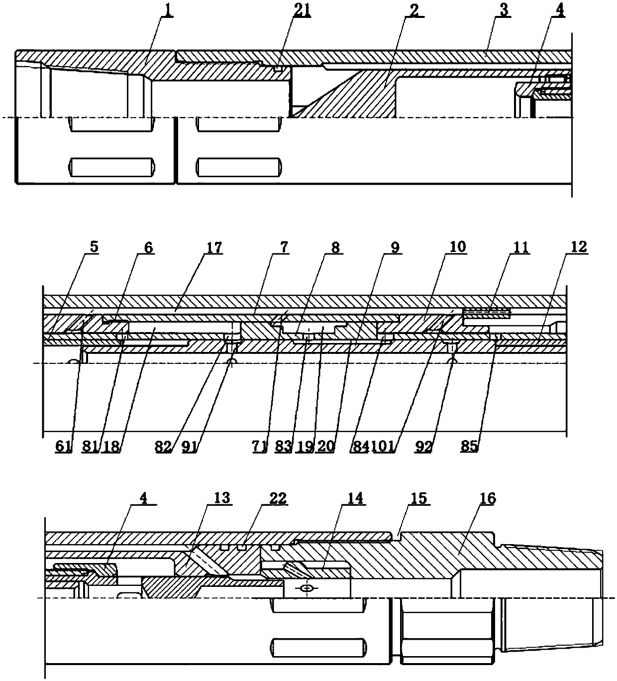
[0029] A hydraulic push-back impact oscillator, the structure is as follows figure 1 As shown, it consists of an upper joint 1, a cylinder body 3 and a lower joint 16 which are threaded sequentially from top to bottom. The cavity of the cylinder body 3 is equipped with a shunt assembly, a reciprocating drive assembly and a back pressure valve assembly. The flow diversion assembly is composed of a diversion sleeve 2, an upper valve body 6, a valve body 7, and a lower valve body 10, which are sequentially set in the cavity of the cylinder body 3. The reciprocating drive assembly is composed of a driving piston 8 and a reversing valve 9. Composition, the driving piston 8 is set in the cavity formed by the upper valve body 6, the valve body 7 and the lower valve body 10, and the lower end of the upper valve body 6 and the upper end of the lower v...


PUM


Abstract

The invention discloses a hydraulic push-back impact oscillator, which consists of an upper joint, a cylinder and a lower joint which are threaded in sequence from top to bottom. Assembly. The diverter assembly is composed of a guide sleeve, an upper valve body, a valve body, a lower valve body and a flow distribution plate. The reciprocating drive assembly is composed of a driving piston and a reversing valve. The back pressure valve assembly is composed of a back pressure valve head, a back pressure valve body and a discharge sleeve. The high-pressure liquid pumped in the device provides hydraulic drive horsepower for the reciprocating drive assembly after being divided by the diverter assembly. The reversing valve controls the drive piston to perform upstroke and downstroke movements, and the drive piston drives the back pressure valve head at the same time. Doing reciprocating motion, the back pressure valve head periodically opens and closes the back pressure valve body, so as to realize the pulsating back pressure-pressure relief process in the pipe string, and at the same time, at the end of each stroke of the driving piston, it will impact the upper valve body or the lower valve body, Thereby generating periodic mechanical shock force at the same time.

Description

technical field [0001] The invention belongs to the technical field of drilling tools for oil and natural gas exploitation, and in particular relates to a hydraulic push-back impact oscillator. Background technique [0002] During the drilling process, the hydraulic oscillator can generate vibration along the axis of the drilling tool assembly or the drill pipe through hydraulic action. During the drilling process, part or all of the drilling tool assembly or the drill pipe is in contact with the well wall, so that friction will be generated during the movement. Vibration along the axis can significantly reduce this friction. Therefore, in all drilling processes, two effects can be produced by reducing friction: it can transfer part of the weight of the drill tool assembly to the drill bit, and reduce the torsional vibration of the drill tool assembly due to friction. [0003] Especially in the directional drilling mode using steerable motors, the frictional resistance gre...

Claims


Application Information

Patent Timeline
Patent Type & Authority Patents(China)
IPC IPC(8): E21B7/24
CPCE21B7/24
Inventor 李云虎王天巧柳小伟郑永哲
Owner BAOJI YUANSHEN PETROLEUM EQUIP NEW TECH CO LTD
Why Eureka
Try Eureka