
Constant-temperature cracking furnace

A cracking furnace and constant temperature technology, applied in the direction of furnaces, furnace types, furnace components, etc., can solve problems such as difficult to achieve constant temperature, large distance, etc., to achieve the effect of avoiding quality deviation, reducing amplitude, and preventing rolling

Pending Publication Date: 2021-02-26
CNBM CHENGDU OPTOELECTRONICS MATERIAL
View PDF6 Cites 0 Cited by
  • Summary
  • Abstract
  • Description
  • Claims
  • Application Information

AI Technical Summary

Problems solved by technology

The temperature measuring components measure the temperature of the silicon carbide external heater. There is a large distance between the internal temperature of the silicon carbide furnace body and the heating components, and there is a large hysteresis between the two, and the control set temperature and the actual temperature will appear. ±30°C fluctuation, it is difficult to reach a constant temperature (±5°C) state

Method used


Image

  • Constant-temperature cracking furnace
  • Constant-temperature cracking furnace

Examples


Embodiment Construction

[0017] In order to enable those skilled in the art to better understand the technical solutions of the present invention, the present invention will be further described in detail below in conjunction with specific embodiments.

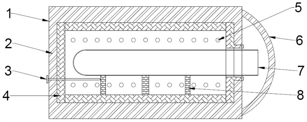
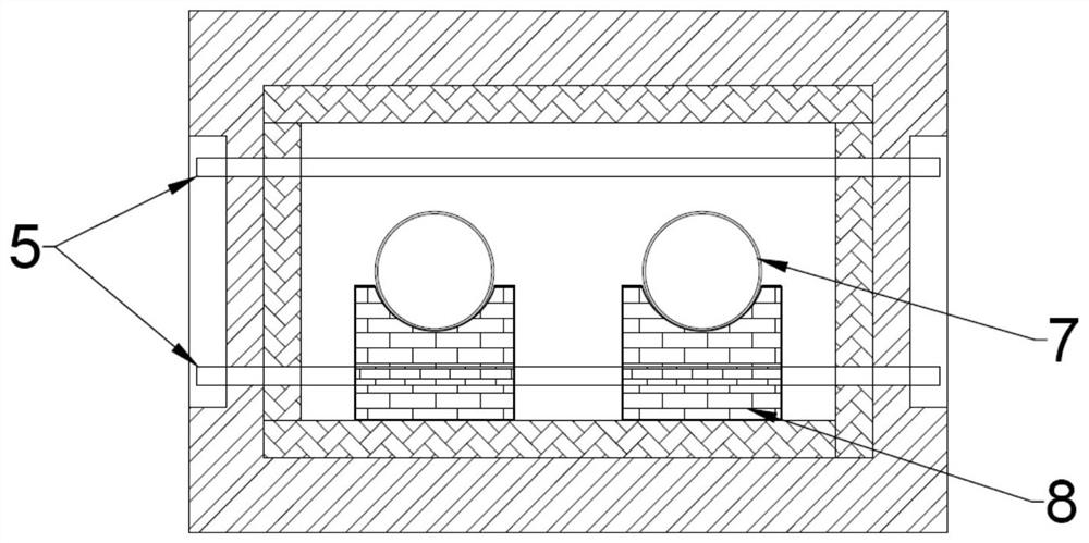
[0018] Such as figure 1 , figure 2 As shown, the present invention includes a furnace body 1, and a furnace door 6 for closing the opening of the furnace body 1; the furnace body 1 is provided with a furnace 4, and the furnace 4 is made of silicon carbide; the upper and lower sides of the furnace 4 are Rod heaters 5 are distributed; the rod heaters 5 are preferably silicon carbide rods, and are evenly distributed on the upper and lower sides of the furnace 4 .

[0019] It also includes a pedestal 8 installed inside the furnace 4 for supporting the quartz tube 7; There are two groups of bases 8 on the left and right, and each group of bases is three sets arranged along the extending direction of the furnace body 1 , which are respectively supported ...


PUM


Abstract

The invention discloses a constant-temperature cracking furnace, comprising a furnace body and a furnace door for sealing an opening of the furnace body. A hearth is arranged in the furnace body and is made of silicon carbide; and rod-shaped heaters are arranged on the upper and lower sides of the hearth. The constant-temperature cracking furnace further comprises a base arranged in the hearth andused for supporting a quartz tube; and a temperature measurement device extends into the hearth from the outer side of the furnace body. The principle of the constant-temperature cracking furnace isthat heat generated by a heating device is directly introduced into the hearth without being transferred through the hearth, and the temperature measurement device also tests the internal temperatureof the hearth, so that hysteresis is not generated during temperature PID control, and the temperature fluctuation is reduced.

Description

technical field [0001] The invention relates to a cracking furnace. Background technique [0002] The tubular cracking furnace is a furnace type commonly used in the cracking process at present. The existing cracking furnace is to turn the cylindrical distillation furnace upside down, and put the quartz tube directly into the circular distillation furnace for heating. The furnace body adopts an external heater, and the heat of the heater first heats the silicon carbide furnace, and then conducts into the furnace through the silicon carbide to heat the product. The temperature measuring components measure the temperature of the silicon carbide external heater. There is a large distance between the internal temperature of the silicon carbide furnace body and the heating components, and there is a large hysteresis between the two, and the control set temperature and the actual temperature will appear. ±30°C fluctuation, it is difficult to reach a constant temperature (±5°C) st...

Claims


Application Information

Patent Timeline
Patent Type & Authority Applications(China)
IPC IPC(8): F27B17/00F27D19/00F27D21/00
CPCF27B17/00F27D19/00F27D21/0014F27D2019/0003
Inventor 彭寿南长斌郑林陈立椿钟光平潘锦功傅干华
Owner CNBM CHENGDU OPTOELECTRONICS MATERIAL
Learn More