A kind of bearing inner diameter automatic detection equipment
An automatic detection and bearing technology, which is applied in the direction of measuring devices, mechanical measuring devices, instruments, etc., can solve the problems of low detection efficiency, increase the labor intensity of detection personnel, and increase costs, so as to reduce human labor, improve detection efficiency and detection accuracy , to avoid the effect of unstable center of gravity
- Summary
- Abstract
- Description
- Claims
- Application Information
AI Technical Summary
Problems solved by technology
Method used
Image
Examples
Embodiment 1
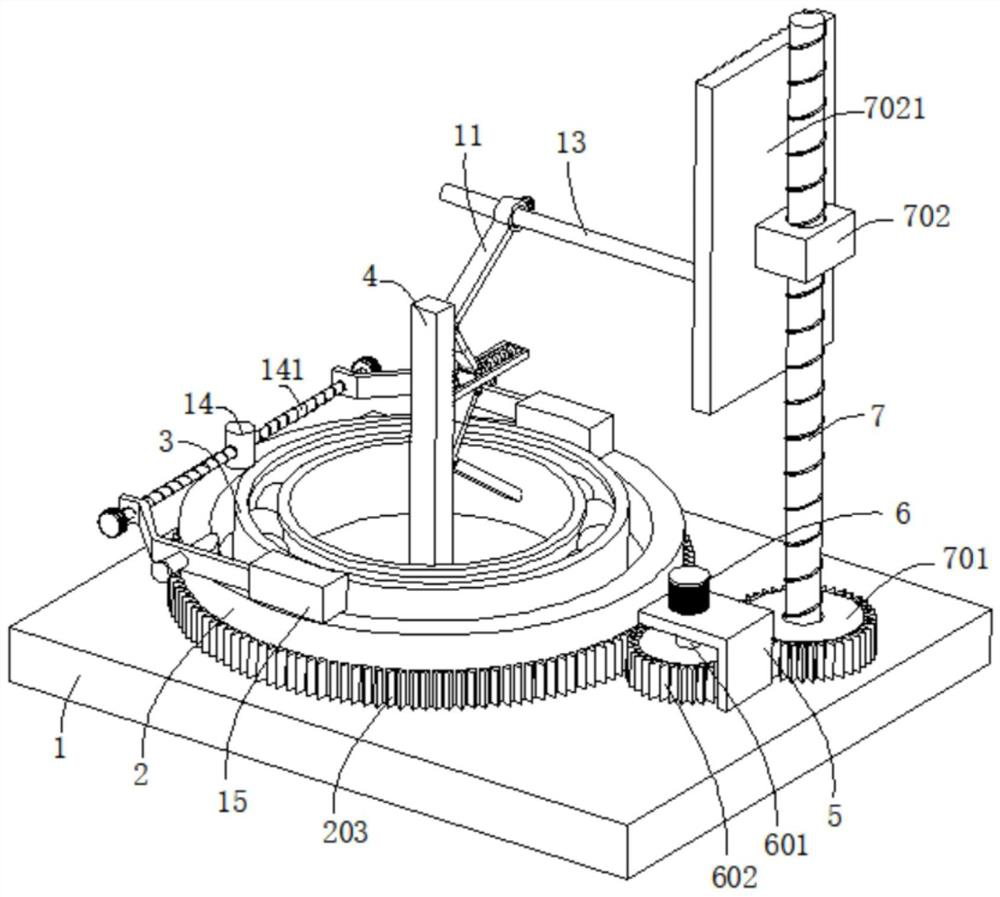
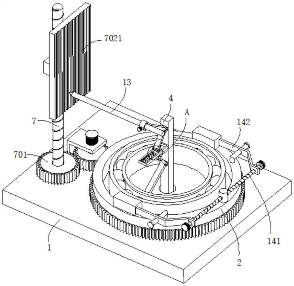
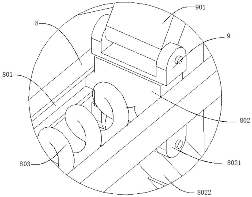
[0030] refer to Figure 1-5 , an automatic detection device for bearing inner diameters, comprising a workbench 1, the top of the workbench 1 is rotatably connected with a storage platform 2, the outer wall of the storage platform 2 is dug with a placement groove 201, the inner wall of the placement groove 201 is connected with a bearing main body 3, and the outer wall of the workbench 1 Connected with a fixed seat 4, the inner wall of the placement groove 201 is dug with a concave hole 202 that matches the fixed seat 4, the central axis of the fixed seat 4 and the placement groove 201 is in the same straight line, and the outer wall of the fixed seat 4 is connected with a detection mechanism and a recording mechanism. The top of the table 1 is connected with a support base 5, the top of the support base 5 is connected with a driving motor 6, the output end of the driving motor 6 is connected with a rotating shaft 601, and the end of the rotating shaft 601 away from the driving...
Embodiment 2
[0035] refer to figure 1 , figure 2 and Figure 7 , an automatic detection device for bearing inner diameters, which is basically the same as that of Embodiment 1. What is further improved is that a positioning rod 14 is fixedly connected to the outer wall of the storage table 2, and a second screw rod 141 is connected to the positioning rod 14 through bearing rotation. The outer wall of the screw rod 141 is threadedly connected with two moving plates 142 , and the outer wall of the moving plates 142 is connected with a clamping plate 15 , and the clamping plate 15 is movable against the bearing main body 3 .
[0036] The outer wall of the clamping plate 15 is dug with an arc-shaped groove 151 .
[0037] The second threaded rod 141 is placed on both sides of the positioning rod 14 in opposite directions of rotation, and the outer wall of the second threaded rod 141 is connected with a second knob 1411 .
[0038] By turning the second knob 1411, the second knob 1411 drives ...
Embodiment 3
[0040] refer to Figure 6-7 , an automatic detection device for the inner diameter of a bearing, which is basically the same as that of Embodiment 1. What is further improved is that the inner thread of the fixing ring 12 is connected with a screw 121, and the outer wall of the screw 121 is connected with a first knob 122, and the screw 121 is far away from the first knob 122. One end is movable against the recording pen 13; by turning the first knob 122, the first knob 122 controls the rotation of the screw rod 121, and then controls the installation and disassembly of the recording pen 13 by the screw rod 121, so that the structure is simple and easy to operate.
[0041] The outer wall of the storage table 2 is connected with a guide rod 16, and the moving plate 142 is slidably connected to the outside of the guide rod 16; the moving plate 142 is slid on the outside of the guide rod 16, on the one hand, the movement of the moving plate 142 can be played as a guide, and on the...
PUM
 Abstract
Description
Claims
Application Information
 - R&D
- Intellectual Property
- Life Sciences
- Materials
- Tech Scout
- Unparalleled Data Quality
- Higher Quality Content
- 60% Fewer Hallucinations
Browse by: Latest US Patents, China's latest patents, Technical Efficacy Thesaurus, Application Domain, Technology Topic, Popular Technical Reports.
© 2025 PatSnap. All rights reserved.Legal|Privacy policy|Modern Slavery Act Transparency Statement|Sitemap|About US| Contact US: help@patsnap.com


