Check patentability & draft patents in minutes with Patsnap Eureka AI!

Electric compactor

A compactor and electric technology, used in instruments, scientific instruments, sampling, etc., can solve the problems of high compaction, affecting test accuracy, uneven sample hammering, etc., and achieve the effect of simple structure and simple control.

Pending Publication Date: 2021-02-26
广东国信工程监理集团有限公司
View PDF16 Cites 0 Cited by
  • Summary
  • Abstract
  • Description
  • Claims
  • Application Information

AI Technical Summary

Problems solved by technology

[0004] The existing compaction instrument uses a hydraulic cylinder to drive the compaction hammer to lift and lower. In the compaction test, the falling distance of the hammer body is not easy to control. With the addition of samples, the distance between the upper surface of the sample and the action end surface of the hammer body The distance between the hammers is getting closer and closer, causing the hammer body to hammer the upper and lower samples unevenly, and the lower sample has a higher degree of compaction than the upper sample, which affects the accuracy of the test.

Method used


Image

  • Electric compactor
  • Electric compactor
  • Electric compactor

Examples


Embodiment 1

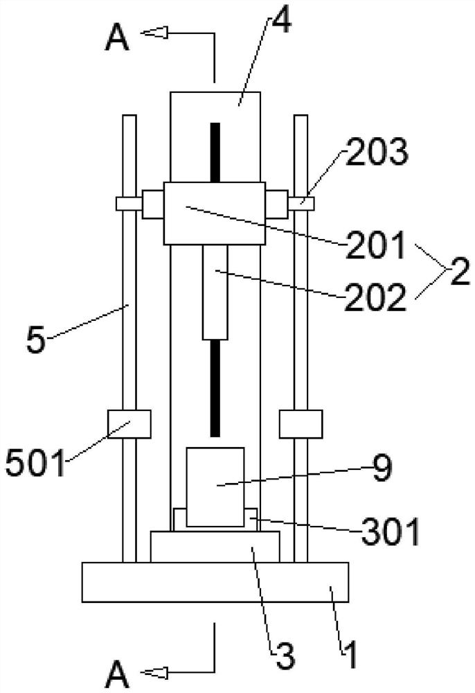
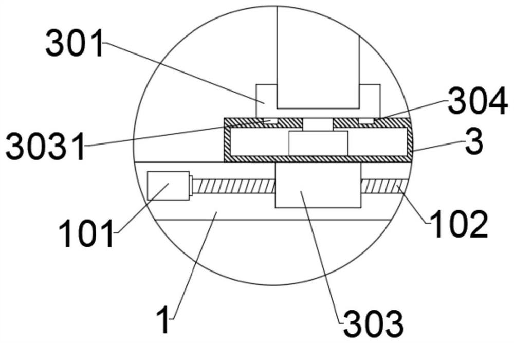
[0039] Such as Figure 1-3 As shown, an electric compaction instrument includes a base 1 and a compaction hammer 2. The base 1 is provided with a rotating base 3 and a lifting base 4. The rotating base 3 is provided with a placing table 301 for placing the test cylinder 9. The lower surface of the table 301 is connected to the driving end of the first rotating motor 302 which is arranged inside the rotating base 3 and can drive it to perform intermittent rotating motions in the horizontal plane;

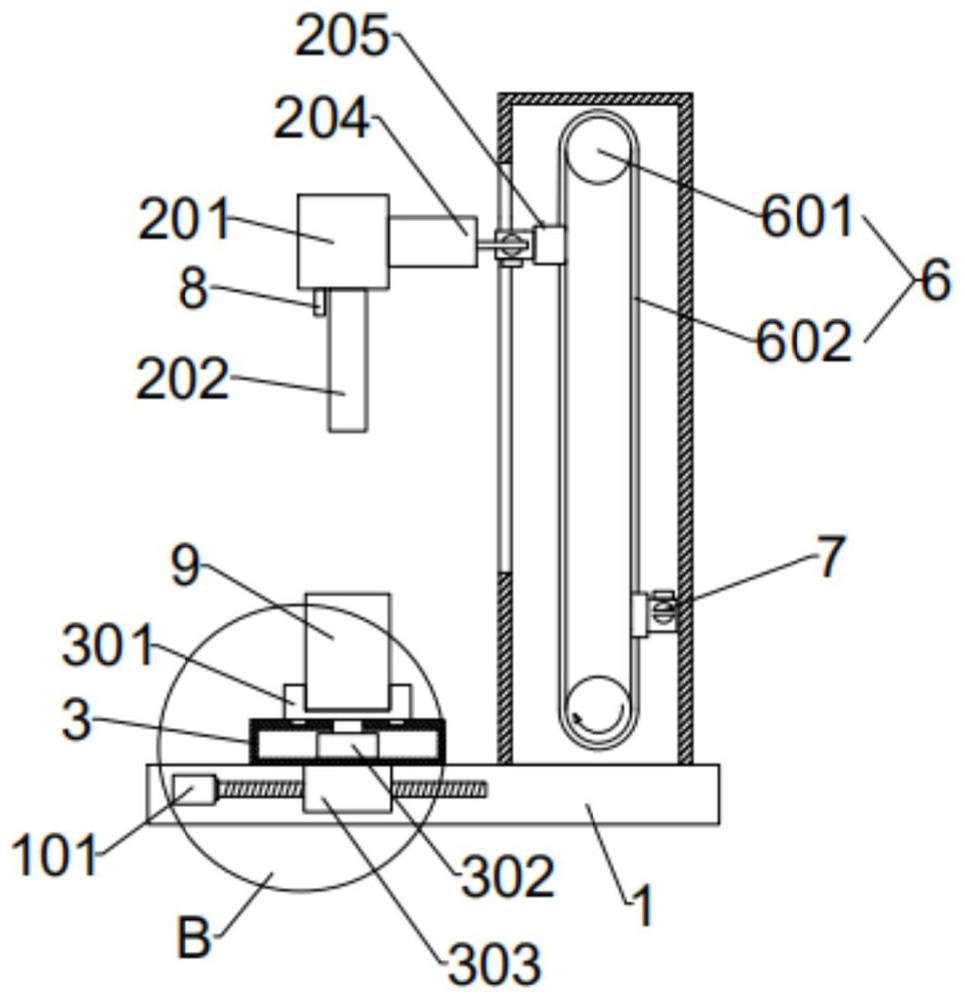
[0040] Also be provided with two vertically arranged guide pillars 5, the guide pillars 5 are respectively located on the left and right sides of the rotating seat 3; The sliding seat 201 is fixedly connected, and the left and right sides of the sliding seat 201 are respectively connected with a sliding ring 203, and the sliding ring 203 is connected with the guide column 5 slidingly up and down; the inside of the lifting seat 4 is provided with a chain transmission mechanism 6, and ...

Embodiment 2

[0052] An electric compaction instrument, comprising a base 1 and a compaction hammer 2, the base 1 is provided with a rotating base 3 and a lifting base 4, the rotating base 3 is provided with a placement table 301 for placing a mold test cylinder 9, and the placement table 301 The lower surface is connected to the driving end of the first rotating motor 302 which is arranged inside the rotating seat 3 and can drive it to perform intermittent rotating motion in the horizontal plane;

[0053] Also be provided with two vertically arranged guide pillars 5, the guide pillars 5 are respectively located on the left and right sides of the rotating seat 3; The sliding seat 201 is fixedly connected, and the left and right sides of the sliding seat 201 are respectively connected with a sliding ring 203, and the sliding ring 203 is connected with the guide column 5 slidingly up and down; the inside of the lifting seat 4 is provided with a chain transmission mechanism 6, and the chain tra...


PUM


Abstract

The invention discloses an electric compactor, which comprises a base and a compaction hammer, the base is provided with a rotating seat and a lifting seat, the rotating seat is provided with a placing table used for placing a test mold cylinder, a chain transmission mechanism is arranged in the lifting seat, and the chain transmission mechanism comprises two chain wheels and an annularly arrangedchain; the chain is fixedly connected with a lifting module, the lifting module comprises a lifting block, a lifting rod and a light receiver, a second driving device is arranged in the lifting block, and the driving end of the second driving device is connected with the lifting rod; the lifting rod stretches and retracts relative to the lifting block under the driving action of the second driving device; and a lifting plate is fixedly connected to the rear side of the sliding seat through a connecting piece, and the lifting plate is matched with the lifting rod. The falling distance of the hammer body can be adjusted according to the internal height of the sample, and the hammering acting force and the compaction degree of the upper-layer sample and the lower-layer sample are ensured tobe consistent.

Description

technical field [0001] The invention relates to the field of geotechnical test equipment, in particular to an electric compaction instrument. Background technique [0002] The compaction instrument is a special instrument used for foundation filling projects such as hydraulic engineering dams, highways, railways, civil aviation airports, municipal engineering, and civil buildings. Under the action of standard compaction work, the relationship between soil moisture content and dry density is measured, so as to determine the optimal moisture content and corresponding maximum dry density of the soil sample. [0003] The indoor compaction test process is: put a sample with a certain water content into the compaction test mold in three or two layers, and hit each layer with a compaction hammer to achieve a certain number of hits. The compaction work is the product of the weight of the hammer body, the drop distance of the hammer body and the number of blows. After the soil layer...

Claims


Application Information

Patent Timeline
Patent Type & Authority Applications(China)
IPC IPC(8): G01N1/28
CPCG01N1/286
Inventor 刘西报覃桂初
Owner 广东国信工程监理集团有限公司
Features
  • R&D
  • Intellectual Property
  • Life Sciences
  • Materials
  • Tech Scout
  • Unparalleled Data Quality
  • Higher Quality Content
  • 60% Fewer Hallucinations
Learn More