Chip heat dissipation structure

A chip heat dissipation, chip technology, applied in the direction of semiconductor/solid-state device parts, semiconductor devices, electrical components, etc., can solve the problems of cost control, radiator space size limitation, etc., to improve production assembly efficiency and increase heat transfer area , Improve the overall cooling effect

Active Publication Date: 2021-02-26
四川长虹空调有限公司
View PDF14 Cites 0 Cited by
  • Summary
  • Abstract
  • Description
  • Claims
  • Application Information

AI Technical Summary

Problems solved by technology

[0003] At the same time, in actual product applications, various conditions such as limited radiator space size restrictions, limited cost control, and limited adjustment ranges for the relative positions of multiple chips are often encountered. Under these c...

Method used


Image

  • Chip heat dissipation structure
  • Chip heat dissipation structure
  • Chip heat dissipation structure

Examples


Embodiment example 1

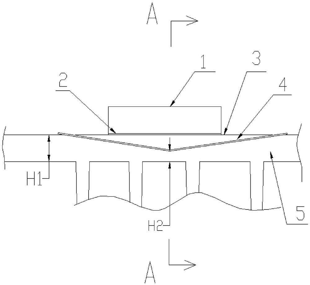
[0041] Implementation Case 1: see figure 1 and figure 2 , the chip 1 (igbt chip) is closely connected to the upper surface of the upper substrate 3 through the thermal conduction layer 2 (silicon grease layer); the material of the upper substrate 3 is the same as that of the lower substrate 5, both of which are aluminum alloy metal. The bottom surface of the upper base 3 is V-shaped, and it is closely connected with the lower base 5 through the insulating heat-conducting gasket 4 (fiber insulating heat-conducting material), and the lower base 5 has a prefabricated matching V-shaped groove. The insulating and heat-conducting gasket 4 is 2 mm to 3 mm beyond the edge of the bottom surface of the upper substrate 3 to ensure effective insulation. The base of the heat sink 9 is a flat plate structure, that is, the thickness is reduced in the groove area corresponding to the upper base 3 . The substrate thickness H1 of the lower substrate 5 is 4 mm, and the substrate thickness at ...

Embodiment example 2

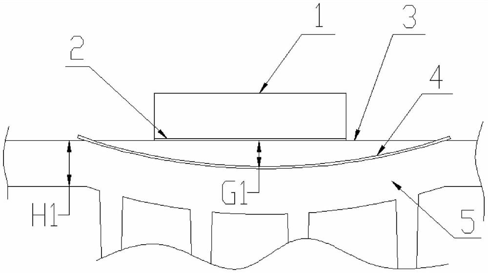
[0043] Implementation Case 2: see image 3 , the chip 1 (igbt chip) is closely connected to the upper surface of the upper substrate 3 through the thermal conduction layer 2 (silicon grease layer); the material of the upper substrate 3 is the same as that of the lower substrate 5, both of which are aluminum alloy metal. The bottom surface of the upper base 3 is an arc-shaped curved surface structure, which is closely connected with the lower base 5 through the insulating heat-conducting gasket 4 (fiber insulating heat-conducting material), and the lower base 5 has a prefabricated matching arc-shaped groove, where the arc-shaped groove is located. The thickness of the position remains consistent with the overall thickness of the substrate, that is, the thickness of the substrate in all regions of the lower base 5 remains unchanged. The insulating and heat-conducting gasket 4 is 2 mm to 3 mm beyond the edge of the bottom surface of the upper substrate 3 to ensure effective insul...

Embodiment example 3

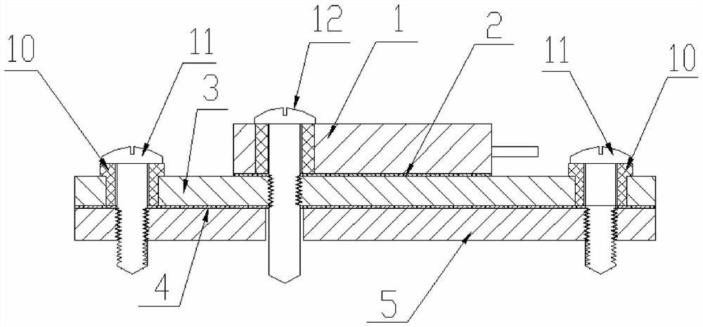
[0045] Implementation Case 3: see Figure 7 , the second chip 6, the chip 1 (igbt chip) and the third chip 7 are sequentially arranged on the heat sink. The second chip 6 is closely connected to the top surface of the lower substrate 5 through the second heat conduction layer 8 (silicon grease layer); the third chip 7 is closely connected to the top surface of the lower substrate 5 through the third heat conduction layer 9 (silicon grease layer). The chip 1 (igbt chip) is closely connected to the upper surface of the upper substrate 3 through the thermal conduction layer 2 (silicon grease layer); the material of the upper substrate 3 is the same as that of the lower substrate 5, both of which are aluminum alloy metal. The bottom surface of the upper base 3 is V-shaped, and it is closely connected with the lower base 5 through the insulating heat-conducting gasket 4 (fiber insulating heat-conducting material), and the lower base 5 has a prefabricated matching V-shaped groove. ...


PUM

PropertyMeasurementUnit
Thicknessaaaaaaaaaa
Thicknessaaaaaaaaaa

Abstract

The invention relates to the technical field of chip heat dissipation, in particular to a chip heat dissipation structure. The heat dissipation structure comprises a base body and a chip, the base body comprises an upper base body and a lower base body, the upper base body and the lower base body are connected through a first screw, an insulating heat conduction gasket is arranged between the upper base body and the lower base body, heat dissipation fins are arranged on the lower base body, and the chip is fixed to the upper surface of the upper base body through a second screw. A heat conduction layer is packed between the chip and the upper surface of the upper substrate, and the first screw and the second screw are each provided with an insulating sleeve. The contact area of the chip and the heat conduction layer is set to be A1, the contact area of the upper base body and the insulating heat conduction gasket is set to be A2, the heat conduction coefficient of the heat conduction layer is set to be K1, the heat conduction coefficient of the insulating heat conduction gasket is set to be K2, and the value of A2:A1 is larger than 1 and smaller than 2K1/K2. The comprehensive heatdissipation effect of a radiator can be reasonably improved.

Description

technical field [0001] The invention relates to the technical field of chip heat dissipation, in particular to a chip heat dissipation structure. Background technique [0002] Generally, in existing chip cooling technologies, a large radiator is basically used to dissipate heat for multiple chips. When the chip contains an igbt chip, due to the special structure and function of the igbt chip, insulation and heat dissipation are required, while other chips basically do not need insulation and heat dissipation. For the IGBT chip, it is usually necessary to use an insulating gasket to connect with the radiator, but the insulating gasket will increase the thermal resistance between the IGBT chip and the metal radiator. Often igbt chip heat dissipation is the bottleneck of the entire chip system heat dissipation. In order to solve this problem, some technical solutions solve it by improving the thermal conductivity of the insulating heat-conducting layer, such as patent documen...

Claims


Application Information

Patent Timeline
IPC IPC(8): H01L23/367H01L23/373
CPCH01L23/3672H01L23/3735H01L23/367H01L23/3736
Inventor 张仁亮戴升龙张红兵
Owner 四川长虹空调有限公司
Why Eureka
Try Eureka