
Eureka
For R&D, Eureka makes reading and utilizing patents & technical documents easy.
Eureka AIR
Designed for self-driven R&D workflows. Generate viable solutions, solve complex R&D challenges, empower your innovation with AI.

Eureka Materials
Designed for material experts only. Revolutionize your material R&D, from search, analyze, to developing new materials.

TechResearch
Generate reliable direction feasibility study reports for your R&D in just a few steps.

TechSeek
Discover and master advanced knowledge NOW. Basics, ideas, possibilities, all at once.

TechMind
As an expert in R&D Theories, TechMind can generates customized viable solutions instantly.

TechRisk
Analyze your overall solution with one click, know your potential R&D risks in advance.

TechMonitor
Get weekly tech updates, stay abreast of the latest tech innovations and key insights.
Power transformation and distribution maintenance device
A technology of fixing plates and fixing rods, which is applied to lifting devices, switch devices, safety devices of lifting equipment, etc., can solve the problems of foot burden, narrow pedals, affecting the work of workers, etc., and achieve the effect of avoiding random movement.
- Summary
- Abstract
- Description
- Claims
- Application Information
AI Technical Summary
Problems solved by technology
Method used
Image

Examples
Embodiment 1
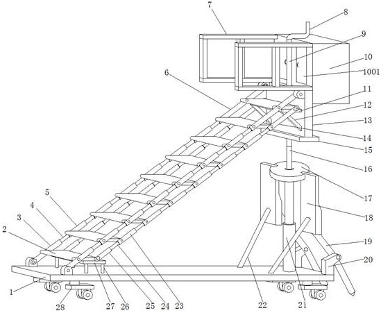
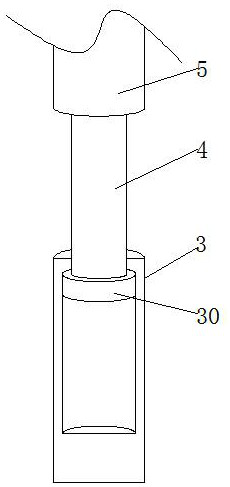
[0031] refer to Figure 1-5 , a maintenance device for substation and power distribution, comprising a base 1, two first fixed rods 3 are rotatably connected to the top of the base 1, a pedal 2 is rotatably connected between the two first fixed rods 3, and one side of the pedal 2 rotates Two fourth fixed rods 25 are connected, and the top ends of the first fixed rod 3 and the fourth fixed rod 25 are respectively provided with several first telescopic groups and second telescopic groups, and the first telescopic group includes the first telescopic rod 4 and the first telescopic group. Moving rod 5, the second telescopic group comprises several second telescopic rods 24 and second moving rod 23, and the top of base 1 is provided with hydraulic system and hydraulic rod 21, and the top of hydraulic rod 21 is provided with the 3rd fixed plate 17, and the 3rd The top of fixed plate 17 is welded with fixed column 16, and the top of fixed column 16 is provided with second fixed plate ...
Embodiment 2
[0044] refer to Figure 6 , a maintenance device for power transformation and distribution. Compared with Embodiment 1, in order to increase the practicability of the device, one side of the guardrail 7 is rotatably connected with a rotating shaft 31, and the middle part of the rotating shaft 31 is welded with a rotating plate 32. The top of the rotating plate 32 is welded with a clamping block 33, and one side of the guardrail 7 is provided with a draw-in groove 701. After the worker reaches the top of the device, the rotating plate 32 is rotated 90 degrees by rotating the rotating plate 32, and the clamping block 33 enters the guardrail. In the draw-in slot 701, the rotating plate 32 is horizontal at this time, and the worker can sit on the rotating plate 32 to prevent the worker from standing for a long time.
[0045] During use, the hydraulic rod 21 is lifted by the hydraulic system, the hydraulic rod 21 drives the second fixed plate 15 to rise, the second fixed plate 15 d...
PUM
 Abstract
Description
Claims
Application Information
 - R&D Engineer
- R&D Manager
- IP Professional
- Industry Leading Data Capabilities
- Powerful AI technology
- Patent DNA Extraction
Browse by: Latest US Patents, China's latest patents, Technical Efficacy Thesaurus, Application Domain, Technology Topic, Popular Technical Reports.
© 2024 PatSnap. All rights reserved.Legal|Privacy policy|Modern Slavery Act Transparency Statement|Sitemap|About US| Contact US: help@patsnap.com