Electric operating device of switch trolley of high-voltage switch cabinet of power system

A high-voltage switchgear and switch trolley technology, applied in switchgear, switchgear parts, pull-out switchgear, etc., can solve the problems of time-consuming, labor-intensive, unutilized, low efficiency, etc., to avoid misoperation safety incidents, The effect of reducing labor intensity and improving work efficiency

Active Publication Date: 2021-02-26
GUIZHOU POWER GRID CO LTD
View PDF15 Cites 2 Cited by
  • Summary
  • Abstract
  • Description
  • Claims
  • Application Information

AI Technical Summary

Problems solved by technology

[0002] The number of removable high-voltage switchgears used in the power system is extremely large. On the one hand, the workload of the switchgear switching trolley operation is relatively large. When encountering switchgear operations, it is time-consuming and laborious. Too heavy will also lead to the situation that the switch trolley is not in place. On the other hand, the position of the switch cabinet switch trolley operating holes is not properly arranged, some are too high, and some are too low, resulting in the need to increase the height when the switch cabinet is operated. The device or squatting (kneeling) on ​​the ground is not conducive to the staff to exert force during operation, and some even the operating handle can only turn half a circle, and the angle of the operating handle must be readjusted, resulting in extremely low efficiency

Method used


Image

  • Electric operating device of switch trolley of high-voltage switch cabinet of power system
  • Electric operating device of switch trolley of high-voltage switch cabinet of power system
  • Electric operating device of switch trolley of high-voltage switch cabinet of power system

Examples


Embodiment 1

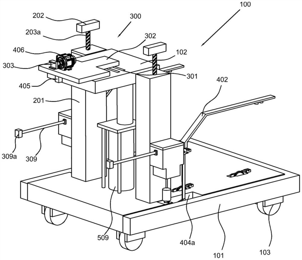
[0028] refer to figure 1 , an electric operating device for a switch trolley of a high-voltage switch cabinet in a power system, comprising a trolley main body 100, an operating platform 101, an operating frame 102 arranged on the operating platform 101, and a driving wheel 103 arranged on the lower surface of the operating platform 101, the driving wheel 103 and the operating platform 101 are provided with a leveling component 500; the operation detection assembly 200 includes a bracket 201 vertically arranged on the operating platform 101, an image and character identification part 202 arranged on the upper end of the bracket 201, and an image character recognition part 202 arranged on the bracket 201 and the adjustment part 203 between the image and character recognition part 202; The adapter 303 and the upper platform 302 protrude outward from the operating frame 102 , the lower surface of the upper platform 302 is provided with an infrared calibrator 405 , and the upper p...

Embodiment 2

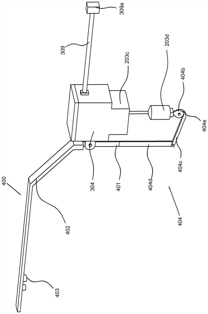
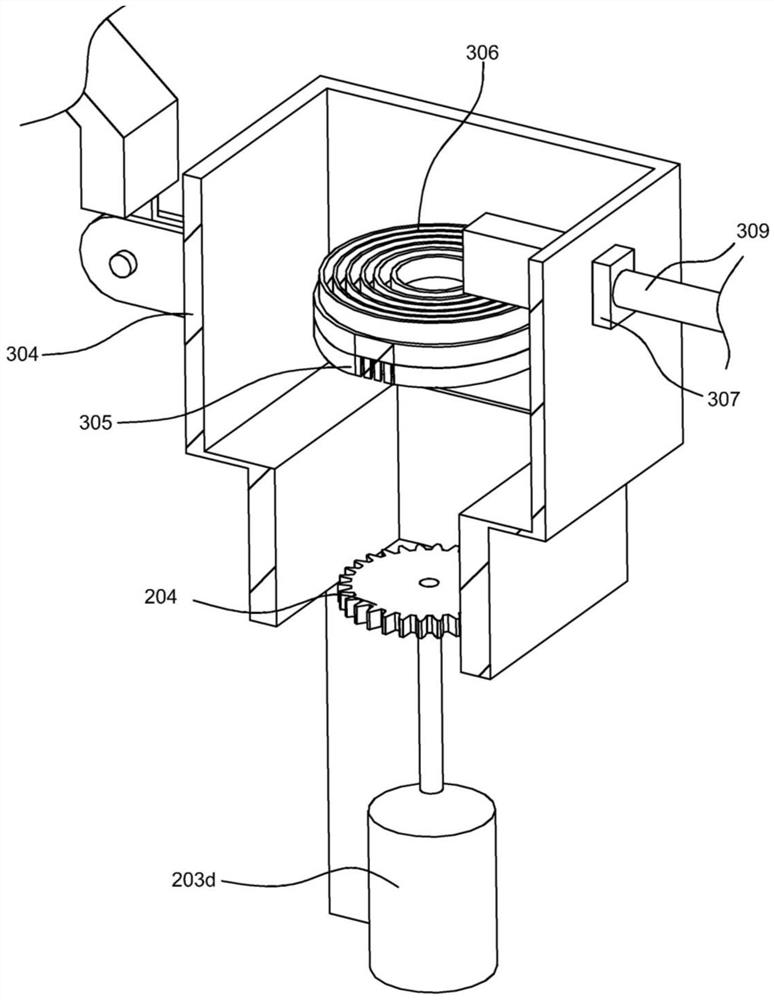
[0034] refer to Figure 1-4 , This embodiment is different from the first embodiment in that: the adjusting part 203 includes a threaded rod 203a vertically arranged in the bracket 201, a rotating cylinder 203b threadedly connected with the threaded rod 203a, and a rotating cylinder 203b arranged at the rear end of the rotating cylinder 203b. Bracket 203c, wherein a stepping motor 203d is provided between the bracket 203c and the operating platform 101, a first gear 204 is provided on the output shaft of the stepping motor 203d, and a first gear 204 meshing with the first gear 204 is provided at the lower end of the rotating cylinder 203b. Two gears 205, the bracket 201 is provided with an opening for the threaded rod 203a to stretch out, the image and character identification part 202 is connected with the upper end of the threaded rod 203a in rotation, and the lower end of the bracket 201 is provided with a horizontal block 304 near the bracket 203c, and the horizontal block ...

Embodiment 3

[0044] refer to Figure 5 , This embodiment is different from the above embodiments in that: the leveling component 500 includes a first adjustment hole 501 opened on the operating platform 101, a first clamping rod 502 slidingly connected in the first adjustment hole 501, and a The first rack 503 on the upper end of the clamping rod 502, the second adjustment hole 504 communicated with the first adjustment hole 501 is provided in the operating platform 101, the second adjustment hole 504 communicates upwards, the first adjustment hole 501 communicates downwards, and the second adjustment hole 501 communicates downwards. A third gear 505 meshing with the first rack 503 is rotatably connected in the adjustment hole 504, and a second lever 506 is rotatably connected to the opening of the second adjustment hole 504, and the front end of the second lever 506 is provided with a wheel with the gear. The flange 507 matched with the teeth, the second clamping rod 506 and the second ad...


PUM


Abstract

The invention discloses an electric operating device for a switch trolley of a high-voltage switch cabinet of a power system. The device comprises a trolley main body, an operation detection assemblyand a guide rail assembly; the trolley main body comprises an operating platform, an operating frame disposed on the operating platform, and a driving wheel disposed on the lower surface of the operating platform; a leveling part is disposed between the driving wheel and the operating platform; the operation detection assembly comprises a support arranged on the operating platform in the verticaldirection, an image character recognition part arranged at the upper end of the support and an adjusting part arranged between the support and the image character recognition part; the guide rail assembly comprises a transverse guide rail arranged on the operating frame, an upper platform connected with the transverse guide rail in a sliding mode and an adapter arranged at the front end of the upper platform.

Description

technical field [0001] The invention relates to the technical field of a switch cabinet trolley, in particular to an electric operating device for a switch trolley of a high-voltage switch cabinet in a power system. Background technique [0002] The number of removable high-voltage switchgears used in the power system is extremely large. On the one hand, the workload of the switchgear switching trolley operation is relatively large. When encountering switchgear operations, it takes time and effort. Too heavy will also lead to the situation that the switch trolley is not in place. On the other hand, the position of the switch cabinet switch trolley operating holes is not properly arranged, some are too high, and some are too low, resulting in the need to increase the height when the switch cabinet is operated. The device or squatting (kneeling) on ​​the ground is unfavorable for the staff to use force during operation, and some even the operating handle can only turn half a c...

Claims


Application Information

Patent Timeline
Patent Type & Authority Applications(China)
IPC IPC(8): H02B11/167H02B11/02
CPCH02B11/167H02B11/02
Inventor 卢兴福王家乐王勋龙波樊三军王竹刘洋陈世丹唐巧巧李宏才汪德生曹俊赵雪娇杨艳栾成龙牟春
Owner GUIZHOU POWER GRID CO LTD
Why Eureka
Try Eureka