Electromagnetic levitation train track system

A magnetic levitation train and electromagnetic levitation technology, which is applied in the field of rail transit, can solve the problems of high leakage magnetic field, large energy consumption of levitation, and low service life, and achieve the effects of reducing the withstand voltage level, reducing costs, and reducing weight

Pending Publication Date: 2021-02-26
DALIAN WHIM SCI & TECH LTD CO
View PDF0 Cites 1 Cited by
  • Summary
  • Abstract
  • Description
  • Claims
  • Application Information

AI Technical Summary

Problems solved by technology

The main problems existing in the prior art are: the electromagnetic levitation system of the EMS magnetic levitation train system is used as both the levitation electromagnet and the traction motor of the linear motor, which is not very efficient, has a weak carrying capacity, and has a large weight and a synchronous linear motor with a traveling wave magnetic field. Complex traction control structure
The superconducting electric levitation train adopts the low-temperature superconducting system, which has obvious electromagnetic radiation during the levitation process. At the same time, it needs rubber wheels to support it at low speed, which consumes a lot of energy. The structure of the superconducting system is more complicated and the cost is high.
The structure of medium and low speed maglev trains is simple, but the driving efficiency of copper or aluminum plates on the top surface of the track and the asynchronous motor at the bottom of the train is very low, the leakage magnetic field of F rail row is high, and the energy consumption of suspension is large
The wheel-rail train has a simple structure and a long service life, but the open wheel-rail structure may derail at any time at high speeds, and the wheel bearings are severely worn under high speed and heavy loads, and their service life is low, requiring frequent repairs and maintenance. Very high, as the train speed increases, the adhesion coefficient between the wheel and the track gradually decreases, making it difficult to brake at high speeds

Method used


Image

  • Electromagnetic levitation train track system
  • Electromagnetic levitation train track system
  • Electromagnetic levitation train track system

Examples


Embodiment Construction

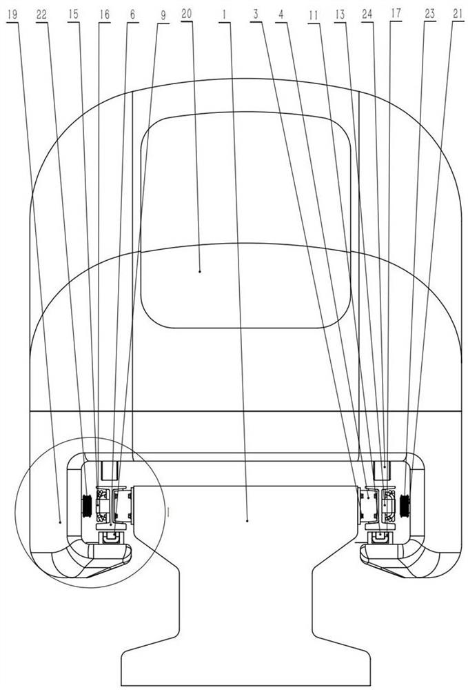
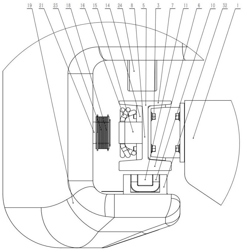
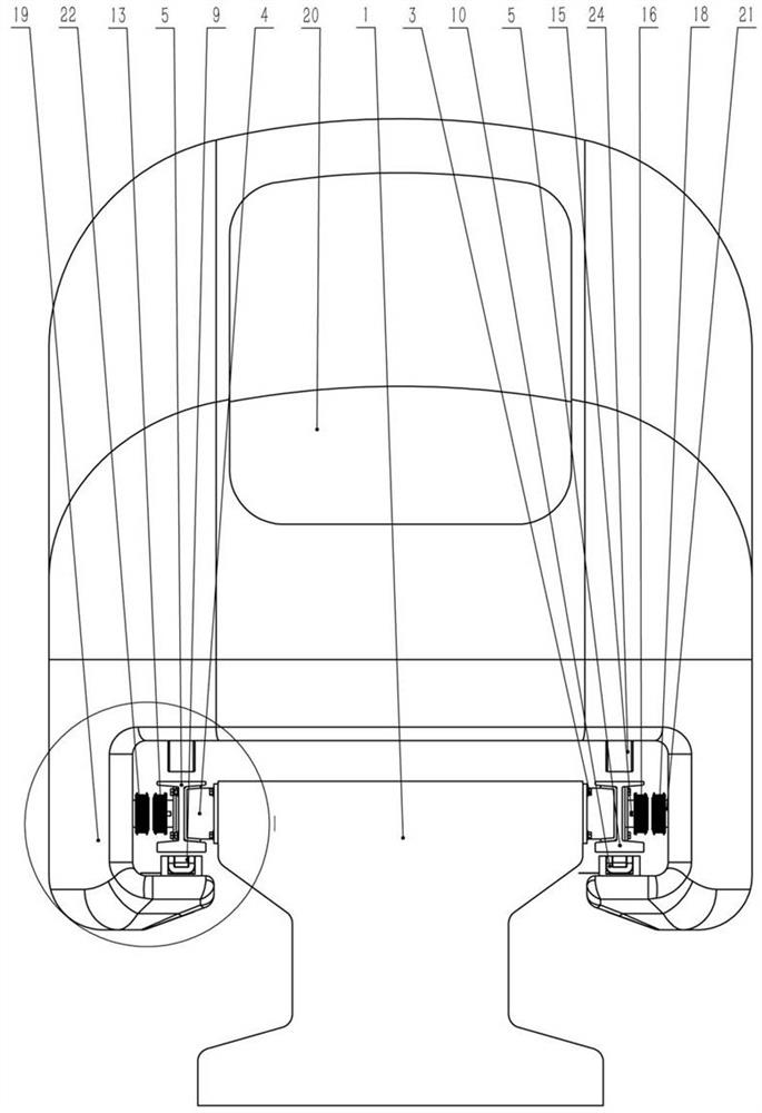
[0076] The present invention is described in further detail now in conjunction with accompanying drawing. Such as figure 1 with figure 2 As shown, it is an electromagnetic levitation train track system of the present invention. Embedded parts are arranged on both sides of the top of the roadbed 1, and track brackets 4 are fixedly arranged on both sides of the embedded parts with fasteners 3, and the extended ends of the track brackets 4 are fixedly connected. The I-shaped steel rail 5, the bottom of the I-shaped steel rail 5 is an armature plate 6, the top of the I-shaped steel rail 5 is a slide plate 7, and the middle is a vertical waist plate 8. The below distance of armature plate 6 is provided with suspending electromagnet 9 in a certain gap, and suspending electromagnet 9 is made of suspending coil 10 and suspending iron core 11, and suspending electromagnet 9 can adopt the electromagnet that can realize the suspending purpose of the present invention in the prior art, ...


PUM


Abstract

The invention provides an electromagnetic levitation train track system, which is characterized in that tracks are arranged on two sides of a roadbed or a track beam, a magnetic levitation train runson the tracks, traction guide electromagnets are horizontally arranged on supporting arms on two sides of the magnetic levitation train, linear motor stators are horizontally arranged at opposite positions on the tracks, the linear motor stator and the traction guide electromagnet are horizontally arranged in the magnetic pole direction, an iron core linear motor is formed by the linear motor stator and the traction guide electromagnet at a certain magnetic gap, and an E-shaped section suspension electromagnet and a gap sensor are arranged at the bottom of the magnetic levitation train and suspended below an armature plate horizontally arranged at the bottoms of the tracks. According to the invention, the control system controls the current and direction of the traction guide electromagnetand the linear motor stator coil, and controls the horizontal guide and suspension force and the traction force and direction, so that the magnetic levitation train flies in the air.

Description

technical field [0001] The invention belongs to the field of rail transportation, and in particular relates to an electromagnetic levitation train track system, which is suitable for a high-speed flying magnetic levitation train track system and a vacuum pipeline magnetic fly train. Background technique [0002] Typical electromagnetic levitation trains that have been put into commercial operation include Germany's EMS system and Japanese superconducting electric levitation trains, and medium and low-speed maglev trains in Japan, China and South Korea. The main problems in the existing technology are: the electromagnetic levitation system of the EMS magnetic levitation train system is not only a levitation electromagnet but also a linear motor traction motor is not very efficient, the load capacity is weak, and there is a synchronous linear motor with a large weight and a traveling wave magnetic field. The traction control structure is complex. There is obvious electromagne...

Claims


Application Information

Patent Timeline
Patent Type & Authority Applications(China)
IPC IPC(8): H02N15/00B60L13/10
CPCH02N15/00B60L13/04E01B25/30E01B25/32B60L2200/26
Inventor 刘忠臣
Owner DALIAN WHIM SCI & TECH LTD CO
Why Eureka
Try Eureka