
Imaging device, unmanned moving body, imaging method, system, and program

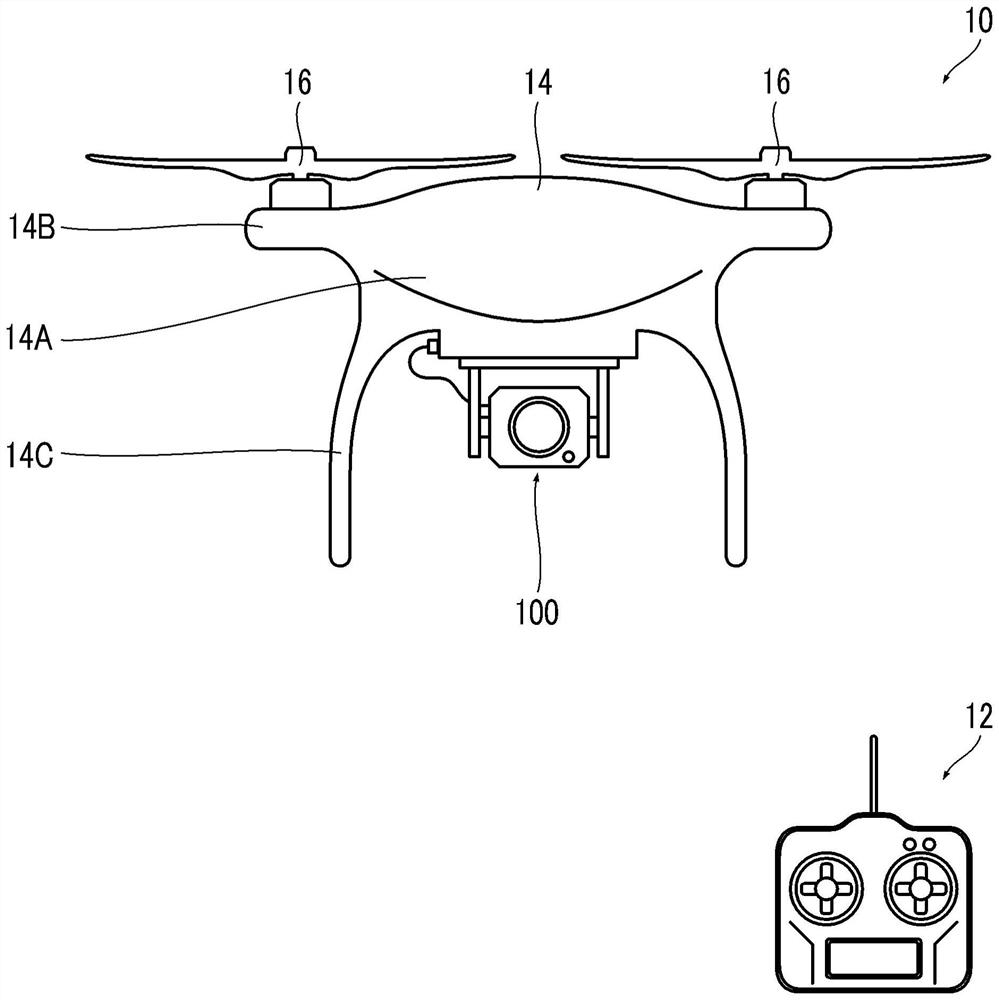
A technology of camera device and camera optical system, which is applied in the field of camera devices, can solve the problems of underexposure of highlight parts and shadow parts, and achieve the effects of reducing the number of shots, less overlapping areas, and high resolution

Active Publication Date: 2021-02-26
FUJIFILM CORP
View PDF9 Cites 1 Cited by
  • Summary
  • Abstract
  • Description
  • Claims
  • Application Information

AI Technical Summary

Problems solved by technology

[0010] When capturing a camera image of a subject (or scene) with a wide dynamic range, sometimes the highlights will be overexposed or the shadows will be underexposed

Method used


Image

  • Imaging device, unmanned moving body, imaging method, system, and program
  • Imaging device, unmanned moving body, imaging method, system, and program
  • Imaging device, unmanned moving body, imaging method, system, and program

Examples


other Embodiment approach

[0301] Next, other embodiments of the present invention will be described.

[0302] Figure 36 It is a functional block diagram showing an embodiment of the image generation unit 301 of this embodiment. Also, yes in Figure 17 The same symbols are attached to the parts already explained in , and explanations are omitted.

[0303] The image generation unit 301 mainly includes a wide dynamic range image generation unit 302 , a determination unit 411 , an image acquisition unit 2 a , a composite information acquisition unit 2 b , and a composite image generation unit 2 c.

[0304] The determination unit 411 determines whether to execute the generation of the wide dynamic range wide-angle image by the wide dynamic range image generation unit 302 based on the magnitude of the light intensity of the wide-angle image. Then, the wide dynamic range image generation unit 302 generates a wide dynamic range wide-angle image only when it is determined by the determination unit 411 that ...


PUM


Abstract

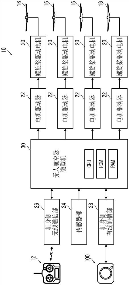
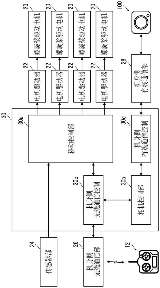
Provided are an imaging device, an unmanned moving body, an imaging method, a system, and a program in which, even when there are few overlapping regions among images included in a telescopic image group, the telescopic image group can be excellently composed, and telescopic images can be composed with high precision, irrespective of a subject (scene) in a wide angle image. An imaging device (100)is provided with: an imaging optical system; a directional sensor; a wide dynamic range image generation unit (302) that generates wide-dynamic-range wide angle images obtained by enlarging the dynamic ranges of wide angle images; an image acquisition unit (2a) that acquires a wide-dynamic-range wide angle image group and a telescopic image group consisting of telescopic images; a composition information acquisition unit (2b) that analyzes the acquired wide-dynamic-range wide angle image group, and acquires composition information which is used for composition of the telescopic image group; and a composite image generation unit (2c) that generates an image by composing the telescopic image group on the basis of the composition information, information about the focal distances of a wide-angle optical system and a telescopic optical system, and the telescopic image group.

Description

technical field [0001] The present invention relates to an imaging device, an unmanned moving object, an imaging method, a system, and a program, and particularly relates to an extended A technique for the dynamic range of acquired camera images. Background technique [0002] There are techniques for combining multiple images to obtain a larger image, known as panorama compositing, stitching, etc. [0003] The mosaic image synthesizing device described in Patent Document 1 combines images with a narrow field of view captured while moving into one image (mosaic image) with a wide field of view, and acquires the information of the camera when each image was captured as information used in the synthesizing. position and posture information. [0004] Also, the position and orientation information of the camera can be estimated by analyzing the image group. Patent Document 1 describes the following procedure, that is, when the position and orientation information of the camera...

Claims


Application Information

Patent Timeline
Patent Type & Authority Applications(China)
IPC IPC(8): H04N5/232H04N7/18H04N5/235G02B13/00G02B17/08G03B7/091G03B15/00G03B19/07G03B37/00G06T5/00G06T5/50H04N5/225
CPCG03B7/091G03B15/00G03B19/07G03B37/00H04N7/18G06T3/4038H04N5/265G02B13/02G02B17/0808H04N23/60H04N23/698H04N23/71H04N23/73G06T5/50H04N23/741H04N23/57
Inventor 小野修司
Owner FUJIFILM CORP
Learn More