Contact network failure detection and diagnosis method based on unmanned aerial vehicle

The technology of an unmanned aerial vehicle and a diagnosis method is applied in the field of catenary fault detection and diagnosis based on the unmanned aerial vehicle, which can solve the problems of increased pollution on the surface of insulators, hidden dangers of locomotive operation, and hidden dangers, and achieve early fault warning. and processing, improving rapidity and real-time performance, and ensuring the effect of railway transportation safety

Active Publication Date: 2011-07-20
SOUTHWEST JIAOTONG UNIV
View PDF3 Cites 39 Cited by
  • Summary
  • Abstract
  • Description
  • Claims
  • Application Information

AI Technical Summary

Problems solved by technology

However, due to the high catenary, the strong vibration of the inspection vehicle, etc., there are limitations in the poor clarity of the catenary image and the difficulty in obtaining the upper image of the catenary, so it cannot completely solve the automation problem of catenary status detection and fault diagnosis
And when the inspection car is working, the normal operation of the railway is affected, that is, there is a problem of repairing the skylight
[0004] Electrical burns account for an increasing proportion of catenary equipment failures, and because of its complex causes and long incubation period, it is difficult to detect early, thus forming a safety hazard; mechanical wear of the contact line exceeding the limit will cause disconnection, directly causing Interruption of railway transportation; due to air pollution, dust and other reas...

Method used


Image

  • Contact network failure detection and diagnosis method based on unmanned aerial vehicle
  • Contact network failure detection and diagnosis method based on unmanned aerial vehicle
  • Contact network failure detection and diagnosis method based on unmanned aerial vehicle

Examples


Embodiment

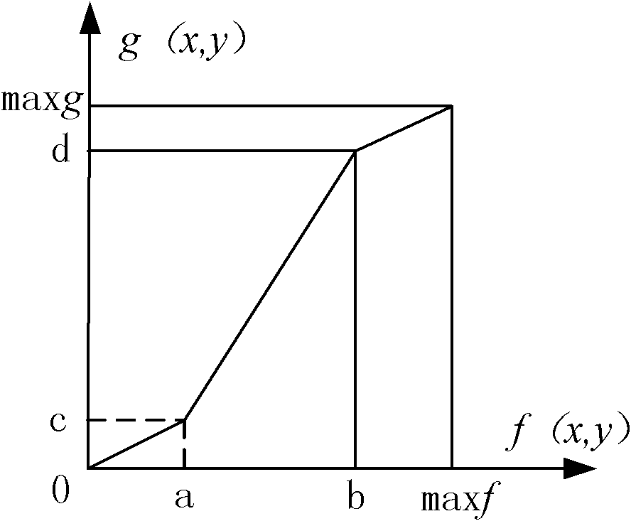
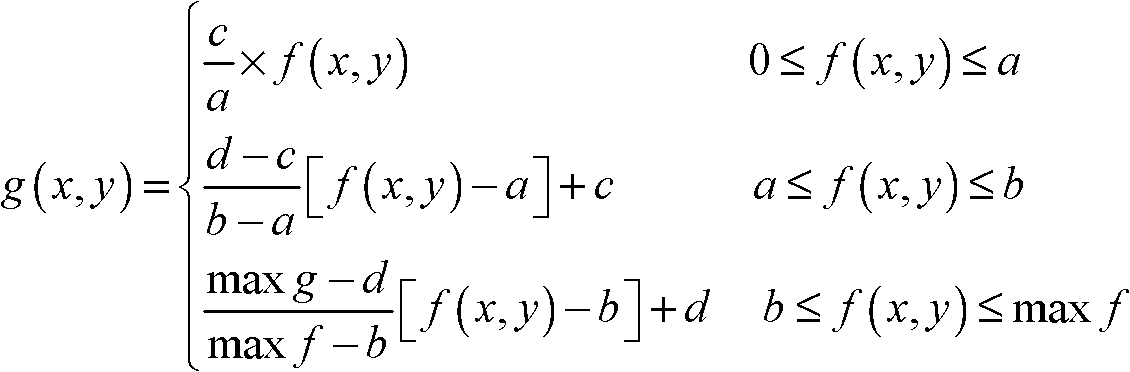
[0030] A kind of embodiment of the present invention is, a kind of catenary fault detection and diagnosis method based on unmanned aerial vehicle, its steps are:

[0031] 1) Image acquisition: The unmanned aerial vehicle carries the camera equipment to take pictures along the catenary, and obtains the catenary images of visible light and infrared light respectively. There are two types of camera equipment carried by UAVs, one is visible light camera equipment, and the other is infrared light camera equipment. Then the visible light catenary image and the infrared light catenary image are processed in steps 2) to 5) respectively:

[0032] 2) Image grayscale: the obtained catenary image is grayscaled to obtain the grayscale image f(x, y) of the catenary.

[0033]The collected image is a color image, which is composed of three basic tones of red, green, and blue. Each pixel of a color image is composed of three basic colors in different proportions. Using the following formula, ...


PUM


Abstract

The invention discloses a contact network failure detection and diagnosis method based on an unmanned aerial vehicle, which comprises the following steps: (1) image acquisition: carrying a video camera to shoot along a contact network by an unmanned aerial vehicle so as to respectively acquire contact network images under visible light and infrared light; (2) image graying; (3) image enhancement; (4) image segmentation; (5) image dissection; (6) image fusion: fusing Laplacian pyramid layers under visible light with corresponding Laplacian pyramid layers under infrared light, and carrying out image reconstruction on the fused Laplacian pyramid to obtain a contact network component image after the visible light image and the infrared light image are fused; and (7) carrying out image identification and failure judgment by a BP (back-propagation) neural network. The method can be used for effectively acquiring a contact network image in the operation process of a locomotive in a multidirectional multiangular real-time mode, automatically identifying the contact network component in the image, and judging whether the contact network fails and the type of the failure; and the judgment result is more accurate and reliable, and can better ensure the safety of railway transportation.

Description

technical field [0001] The invention relates to the field of catenary fault detection and diagnosis for electrified railways, in particular to a catenary fault detection and diagnosis method based on an unmanned aerial vehicle. Background technique [0002] The catenary is a special line erected along the electrified railway line. The electric energy of the electric locomotive is obtained through the sliding friction contact between the pantograph and the catenary. Therefore, catenary is the power lifeblood of electrified railway, which is directly related to the safety of railway transportation. With the increasing mileage of electrified railways in my country and the increasing requirements for the reliability and safety of railway transportation, the detection and maintenance of catenary is becoming more and more arduous and difficult. [0003] Electrified railway catenary detection and fault diagnosis are divided into three categories: functional, state and engineering ...

Claims


Application Information

Patent Timeline
IPC IPC(8): G06K9/62G06N3/02
Inventor 何正友丁雪成马磊林圣
Owner SOUTHWEST JIAOTONG UNIV
Why Eureka
Try Eureka