
Aluminum alloy semi-solid slurry preparation device, die-casting equipment and die-casting process

A technology for semi-solid slurry and preparation device, which is applied in the field of aluminum alloy casting, and can solve the problems of untimely feeding and shrinking between microscopic dendrites

Pending Publication Date: 2021-03-02
CITIC DICASTAL
View PDF0 Cites 1 Cited by
  • Summary
  • Abstract
  • Description
  • Claims
  • Application Information

AI Technical Summary

Problems solved by technology

Due to the unavoidable air entrainment phenomenon, solidification shrinkage of aluminum alloy and untimely feeding and shrinkage between microscopic dendrites in the conventional liquid high-pressure casting process, quality problems such as internal pores, macroscopic and microscopic shrinkage cavities often occur in the production process, Has become an urgent problem to be solved in the field of high pressure casting

Method used


Image

  • Aluminum alloy semi-solid slurry preparation device, die-casting equipment and die-casting process
  • Aluminum alloy semi-solid slurry preparation device, die-casting equipment and die-casting process
  • Aluminum alloy semi-solid slurry preparation device, die-casting equipment and die-casting process

Examples


Embodiment 1

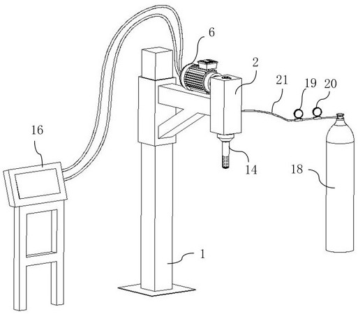
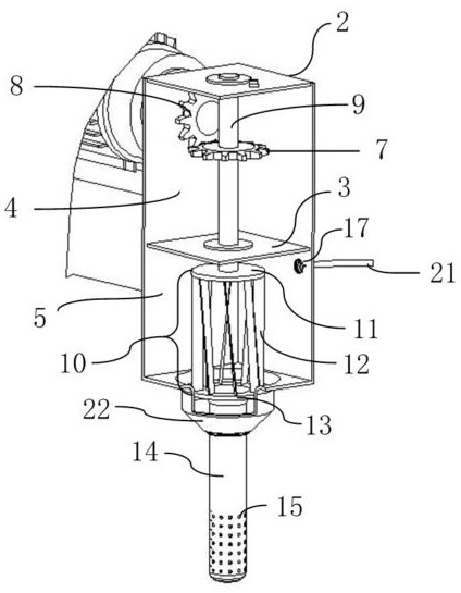
[0030] An aluminum alloy semi-solid slurry preparation device is disclosed in Example 1, such as Figure 1-2 As shown in , including a support 1, a nitrogen supply device and a stirring device, the support 1 is used to install the stirring device. The stirring equipment includes a box body 2 , a sealing baffle 3 , a motor 6 , a driven gear 7 , a motor gear 8 , a connecting rod 9 , a blade disc 10 , a rotor 14 , and a control panel 16 . A sealing baffle 3 is arranged in the box 2, and the sealing baffle 3 divides the box 2 into an upper box 4 and a lower box 5. Connecting rod 9 is set in described upper box body 4, as figure 2 As shown in , the upper part of the connecting rod 9 is rotatably fixed on the top surface of the box body 2 (for example, through a bearing), and the lower part of the connecting rod 9 is rotatably fixed on the sealing baffle 3 . The connecting rod 9 is fixed at the center of the driven gear 7, the output shaft of the motor 6 is fixed at the center of...

Embodiment 2

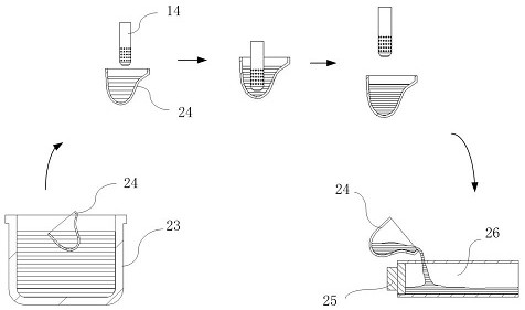
[0036] Embodiment 2 provides a die-casting equipment for aluminum alloy castings, including a holding furnace 23, a soup feeder, a die-casting machine, a casting mold, and an aluminum alloy semi-solid slurry preparation device as described in Embodiment 1. Wherein the die casting machine includes a punch 25 and a pressure chamber 26 . The soup dispenser includes a spoon 24, which is used to transport the molten aluminum from the holding furnace 23 to the pressure chamber 26 of the die-casting machine.

[0037] A die-casting process for aluminum alloy castings of a die-casting equipment for aluminum alloy castings described in Example 2 includes the following steps, such as image 3 As shown in: Set and control the temperature of the aluminum alloy liquid in the holding furnace to 625±5°C, take the aluminum alloy liquid from the holding furnace with a spoon, and transport it to the rotor of the aluminum alloy semi-solid slurry preparation device Below: the rotor physically sti...


PUM


Abstract

The invention relates to the technical field of aluminum alloy casting, and provides an aluminum alloy semi-solid slurry preparation device, die-casting equipment and a die-casting process. Nitrogen supply equipment conveys nitrogen to stirring equipment; a motor in the stirring equipment drives a connecting rod, a fan blade disc and a rotor to rotate so as to implement rotary stirring; meanwhile,the nitrogen is blown into a cavity of the rotor through rotation of the fan blade disc; air blowing is implemented through air blowing holes; and stirring and air blowing are integrated to rapidly prepare aluminum alloy semi-solid slurry, so that the aluminum alloy semi-solid slurry can be rapidly prepared in the die-casting production process of aluminum alloy castings, the content of defects such as pores and shrinkage cavities in high-pressure castings is effectively reduced or eliminated, and the problem of defects in the castings is solved.

Description

technical field [0001] The application relates to the technical field of aluminum alloy casting, in particular to an aluminum alloy semi-solid slurry preparation device, die-casting equipment and a die-casting process. Background technique [0002] With the increasingly stringent requirements of the automotive industry for lightweight, green environmental protection, energy saving and emission reduction, the automotive aluminum casting parts, especially the high pressure casting business, is developing rapidly, and the product coverage is increasing day by day, and it is still developing at an astonishing speed. Due to the unavoidable air entrainment phenomenon, solidification shrinkage of aluminum alloy and untimely feeding and shrinkage between microscopic dendrites in the conventional liquid high-pressure casting process, quality problems such as internal pores, macroscopic and microscopic shrinkage cavities often occur in the production process, It has become an urgent p...

Claims


Application Information

Patent Timeline
IPC IPC(8): B22D1/00B22D17/00B22D17/20
CPCB22D1/00B22D1/005B22D17/007B22D17/20
Inventor 曹文海万雅春陈志黄永跃戴川周磊刘兴富徐佐武汉琦
Owner CITIC DICASTAL
Learn More