Electric vehicle driving system with stepless speed changing function

A driving system and infinitely variable speed technology, which is applied in the direction of electric power devices, vehicle gearboxes, components with teeth, etc., can solve the problems of electric vehicle speed changes and inability to change gears, and achieve the effect of changing the speed of trams

Pending Publication Date: 2021-03-02
SUPERSOCO INTELLIGENT TECHNOLOGY (SHANGHAI) CO LTD
View PDF5 Cites 2 Cited by
  • Summary
  • Abstract
  • Description
  • Claims
  • Application Information

AI Technical Summary

Problems solved by technology

[0004] The existing electric vehicle drive system generally only has one speed gear, and it is impossible to change the gear according to actual needs, so as to realize the speed change of the electric vehicle

Method used


Image

  • Electric vehicle driving system with stepless speed changing function
  • Electric vehicle driving system with stepless speed changing function
  • Electric vehicle driving system with stepless speed changing function

Examples


Embodiment 1

[0025]The existing electric vehicle drive system generally has only one speed gear, and it is impossible to change the gear according to actual needs, thereby changing the speed change of the electric vehicle. Therefore, in this embodiment, the gearbox is set to realize the speed change of the electric vehicle. Variety.

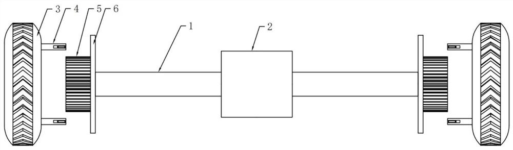
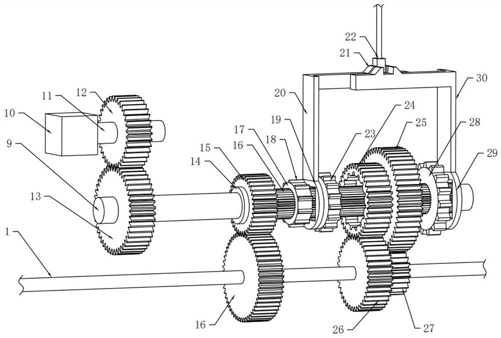
[0026]SeeFigure 1-3, An electric vehicle drive system with stepless speed change, comprising a drive shaft 1 and tires 3, the drive shaft 1 is provided with a gearbox 2, the gearbox 2 is rotatably connected with the drive shaft 1, the gearbox 2 One-speed driven gear 16, a second-speed driven gear 26, and a third-speed driven gear 27 are fixedly installed on the drive shaft 1 in turn from left to right. The gearbox 2 is rotatably connected with a first rotating shaft 9. The first rotating shaft 9 is fixedly mounted with a bearing 14. The bearing 14 on the first rotating shaft 9 is connected to the first-speed driving gear 15, the second-speed driving gear 24, and the t...

Embodiment 2

[0029]Existing drive shafts and tires are generally fixed by bolts. When maintenance is required, it is particularly difficult to disassemble, which makes it difficult to repair. Therefore, in this embodiment, a clamping assembly is provided to achieve more convenient disassembly and more convenient Maintenance.

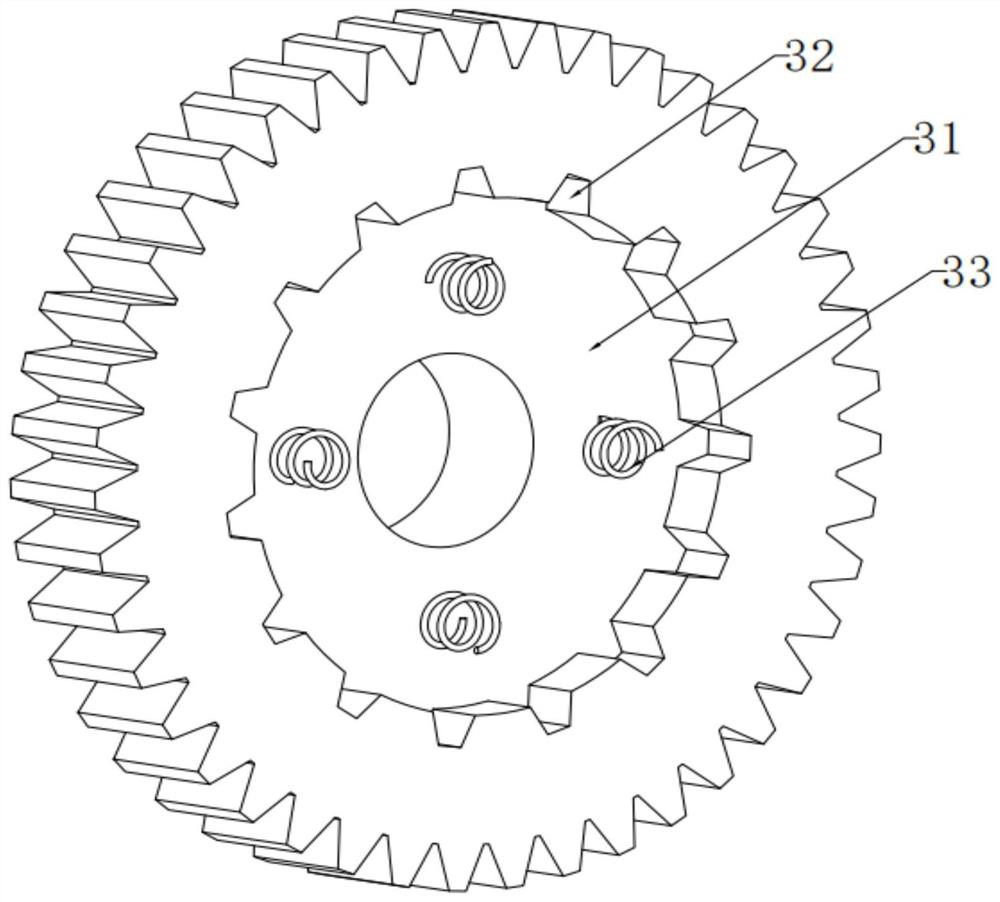
[0030]SeeFigure 4 with5, The left and right ends of the drive shaft 1 are fixedly installed with second clamping teeth 5, the tire 3 is provided with a second clamping groove 8, and the second clamping teeth 5 are arranged corresponding to the second clamping groove 8, so The tire 3 is provided with a clamping assembly 4, the drive shaft 1 is fixedly mounted with a connecting disc 6, and the connecting disc 6 is provided with a fixing hole 7, and the clamping assembly 4 is arranged corresponding to the fixing hole 7, so The clamping assembly 4 includes a clamping rod 401, a second groove 402 is opened on the clamping rod 401, a clamping block 403 is rotatably connected to the...


PUM


Abstract

The invention discloses an electric vehicle driving system with a stepless speed changing function. The electric vehicle driving system comprises a driving shaft and tires. A gearbox is arranged on the driving shaft and rotatably connected with the driving shaft, and a first-gear driven gear, a second-gear driven gear and a third-gear driven gear are fixedly installed on the portion, in the gearbox, of the driving shaft in sequence from left to right. A first rotating shaft is rotatably connected to the gearbox, a bearing is fixedly installed on the first rotating shaft, and a first-gear driving gear, a second-gear driving gear and a third-gear driving gear are rotatably connected to the bearing on the first rotating shaft in sequence from left to right. The first-gear driving gear, the second-gear driving gear and the third-gear driving gear are engaged with the first-gear driven gear, the second-gear driven gear and the third-gear driven gear in sequence. The speed of an electric vehicle is changed by arranging the gearbox.

Description

Technical field[0001]The invention relates to the field of design and manufacture of electric vehicles, in particular to an electric vehicle drive system with stepless speed change.Background technique[0002]Electric vehicles are powered by on-board power sources and use motors to drive wheels, which are in line with road traffic and safety[0003]Vehicles required by all regulations. As the environmental impact is relatively small compared to traditional cars, its prospects are widely optimistic. The driving methods of electric vehicles are mainly divided into two types: the traditional centralized drive structure type and the distributed drive electric vehicle structure type.[0004]The existing electric vehicle drive system generally only has one speed gear, and cannot change the gear according to actual needs, so as to realize the speed change of the electric vehicle.Summary of the invention[0005]The purpose of the present invention is to provide an electric vehicle drive system with...

Claims


Application Information

Patent Timeline
IPC IPC(8): F16H3/091F16H55/17F16H63/32B60B37/00B60K1/00
CPCB60B37/00B60K1/00F16H3/006F16H3/091F16H63/32F16H2003/0818F16H2200/0021F16H2200/0039F16H2200/2038
Inventor 谢玉贤赵兴华姚挺
Owner SUPERSOCO INTELLIGENT TECHNOLOGY (SHANGHAI) CO LTD
Why Eureka
Try Eureka