
Plate-fin type heat exchanger core

A plate-fin heat exchanger and plate-fin technology, applied in the field of plate-fin heat exchangers, can solve the problems of inability to realize refined production, high leakage rate of core body, low assembly efficiency, etc., and achieve easy distribution of production, Reduced leakage rate and simple parts

Pending Publication Date: 2021-03-02
沈阳华铁异型材有限公司
View PDF0 Cites 0 Cited by
  • Summary
  • Abstract
  • Description
  • Claims
  • Application Information

AI Technical Summary

Problems solved by technology

[0004] Aiming at the problems of various types and quantities of plate-fin structure parts of all-aluminum radiators, difficult assembly, low assembly efficiency, high core leakage rate, and inability to realize refined production, the purpose of the present invention is to provide a plate-fin heat exchanger Core, to simplify the type and quantity of core parts, reduce the core leakage rate, facilitate core assembly and size control

Method used


Image

  • Plate-fin type heat exchanger core
  • Plate-fin type heat exchanger core
  • Plate-fin type heat exchanger core

Examples


Embodiment 1

[0032] Such as Figure 5-9 As shown, the core body of the plate-fin heat exchanger of the present invention includes a side plate 1, a heat dissipation strip 4, a cooling pipe assembly 7 and a seal assembly 8, wherein a plurality of heat dissipation strips 4 are arranged between the side plates 1 on both sides. And a plurality of cooling pipe assemblies 7, each cooling belt 4 and each cooling pipe assembly 7 are arranged alternately.

[0033] The cooling pipe assembly 7 of this embodiment includes a plate-fin single-hole tube 701 and an inner fin 6 welded in the plate-fin single-hole tube 701. The plate-fin single-hole tube 701 is integrally formed, and the sealing performance is obvious Higher than the sealing performance of the existing core body through the internal channel 5 that is welded together, the leakage rate of the core body is reduced; the end face of the plate-fin single-hole tube 701 in this embodiment is a rectangle, and the inner surfaces of the left and right...

Embodiment 2

[0041] Such as Figure 5-7 and Figure 10As shown, the difference between the present embodiment and the first embodiment is that the welded assembly of the present embodiment includes an extruded groove 805 and a separator / double-coated aluminum strip 806, and extruded seals are provided on both sides of the end surface of the extruded seal 801. Groove 805, there are two extrusion grooves 805 on each side in this embodiment, and the separator / double-coated aluminum strip 806 on each side is extruded in the extrusion groove 805, and then fixed with the extrusion seal 801; in this embodiment Both ends of the separator / double-clad aluminum strip 806 are bent toward one side of the extruded seal 801, and then bent outward, and the bent part is extruded in the extruded groove 805. When it is a partition, there is solder on the inner and outer surfaces of the partition, and the solder melts during brazing so that the partition is welded and sealed with the extrusion seal 801 and t...


PUM


Abstract

The invention belongs to the field of plate-fin type heat exchangers, and particularly relates to a plate-fin type heat exchanger core. The plate-fin type heat exchanger core comprises side plates, heat dissipation belts, cooling pipe assemblies and sealing strip assemblies; a plurality of heat dissipation belts and a plurality of cooling pipe assemblies are arranged between the side plates on thetwo sides; the heat dissipation belts and the cooling pipe assemblies are arranged alternately; each cooling pipe assembly comprises a plate-fin type single-hole pipe and an inner fin welded in the plate-fin type single-hole pipe; sealing strip assemblies are arranged at the two ends of each heat dissipation strip; each sealing strip assembly comprises an extrusion sealing strip and a welding wire; welding wire grooves are formed in the two sides of the end face of each extrusion sealing strip respectively; the welding wires are accommodated in the welding wire grooves respectively; the welding wires are melted in the brazing process, and then the extrusion sealing strips and the adjacent cooling pipe assemblies are welded and sealed, and then a core body is formed. According to the plate-fin type heat exchanger core, the types and number of parts of an existing plate-fin type heat exchanger core are reduced, the assembling efficiency is improved, core size control is facilitated, assembly line step-by-step production is facilitated, the leakage rate of the plate-fin type heat exchanger core is reduced, and meanwhile, the product appearance is improved.

Description

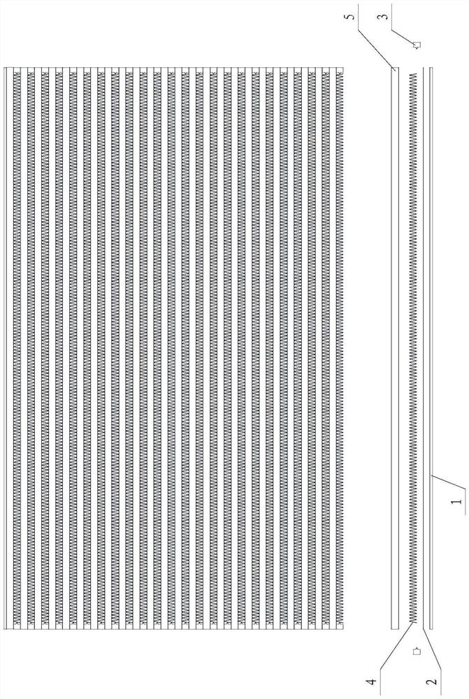
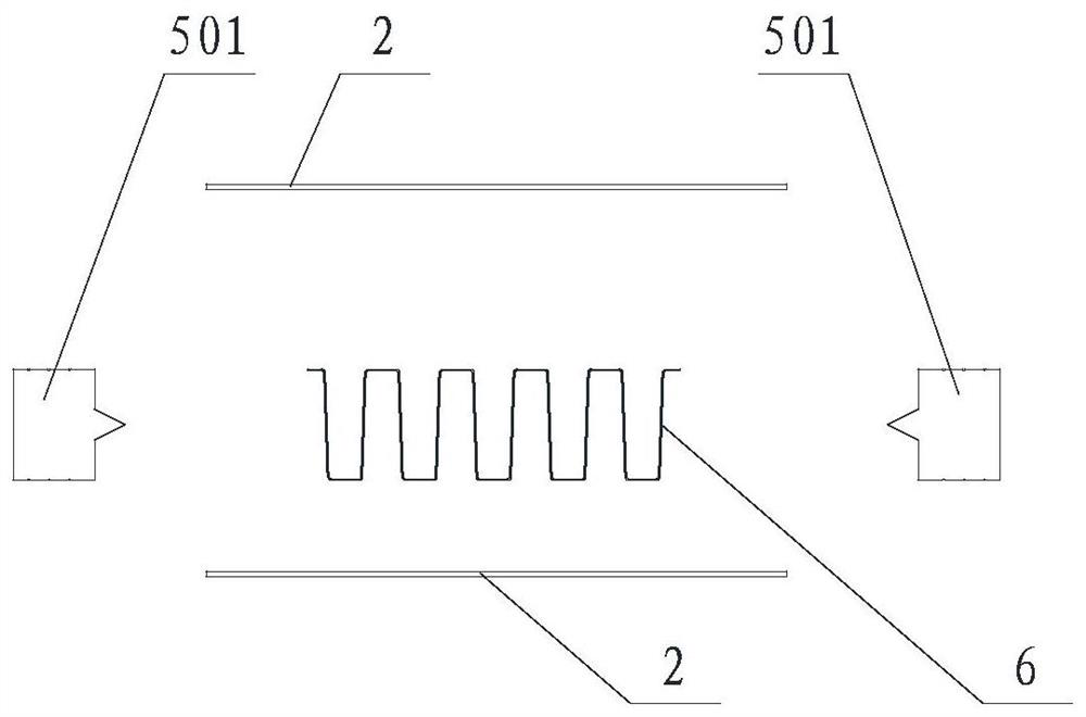
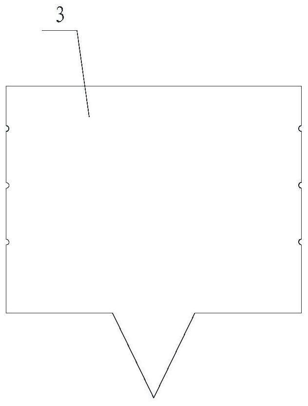
technical field [0001] The invention belongs to the field of plate-fin heat exchangers, in particular to a core body of the plate-fin heat exchanger. Background technique [0002] Such as Figure 1~4 As shown, the parts required for assembly of the existing plate-fin heat exchanger core include side plate 1, aluminum strip separator 2, short seal 3, heat dissipation belt 4 and internal channel 5, and internal channel 5 includes two long seals 501, two upper and lower aluminum strip partitions 2 and inner fins. The assembly sequence of the core body of the existing plate-fin heat exchanger is as follows: side plate 1, aluminum strip partition 2, heat dissipation strip 4, short seals 3 placed at both ends of the heat dissipation strip 4, and an aluminum strip partition forming the internal channel 5 2. Place long seals 501 at both ends of the aluminum strip partition 2, place inner fins 6 between the two long seals 501, place another aluminum strip partition 2 forming the int...

Claims


Application Information

Patent Timeline
Patent Type & Authority Applications(China)
IPC IPC(8): F28D9/00F28F3/06F28F3/10
CPCF28D9/0037F28F3/06F28F3/10
Inventor 石铁光徐家钜曲祥东关越孙续强钱宏林石晶段涛
Owner 沈阳华铁异型材有限公司
Learn More