A bomb support device for automatic loading of bombs and its application method

An automatic loading and projectile technology, applied in the direction of ammunition supply, offensive equipment, weapon accessories, etc., can solve the problems of increased risk, reverse loading, large volume and weight, etc., and achieve the effect of improving safety and saving manufacturing costs.

Active Publication Date: 2022-03-22
NANJING UNIV OF SCI & TECH
View PDF8 Cites 0 Cited by
  • Summary
  • Abstract
  • Description
  • Claims
  • Application Information

AI Technical Summary

Problems solved by technology

Most mortars need to be manually loaded from the muzzle when in use. The projectile slides down by its own gravity and hits the firing pin at the bottom for firing. This loading method is prone to accidents such as repeated loading or reverse loading in actual use.
When manually loading large-caliber mortar shells, due to the large volume and weight of the shell, it is difficult to manually load from the muzzle, the efficiency is low, and it is easy to fatigue the combatants and increase the danger.
The automatic loading technology of mortars can solve the above problems well, but at present, most of the mechanisms used for clamping projectiles in the automatic loading technology are full-wrapped structures, which are complicated and costly to manufacture, which is not conducive to equipment maintenance and post-production. Applicable to the transformation and upgrading of different bullet diameters and bullet types

Method used


Image

  • A bomb support device for automatic loading of bombs and its application method
  • A bomb support device for automatic loading of bombs and its application method
  • A bomb support device for automatic loading of bombs and its application method

Examples


Embodiment Construction

[0032] In order to make the object, technical solution and advantages of the present invention clearer, the present invention will be further described in detail below in conjunction with the accompanying drawings and embodiments. It should be understood that the specific embodiments described here are only used to explain the present invention, not to limit the present invention.

[0033] The implementation of the present invention will be described in detail below in conjunction with specific embodiments.

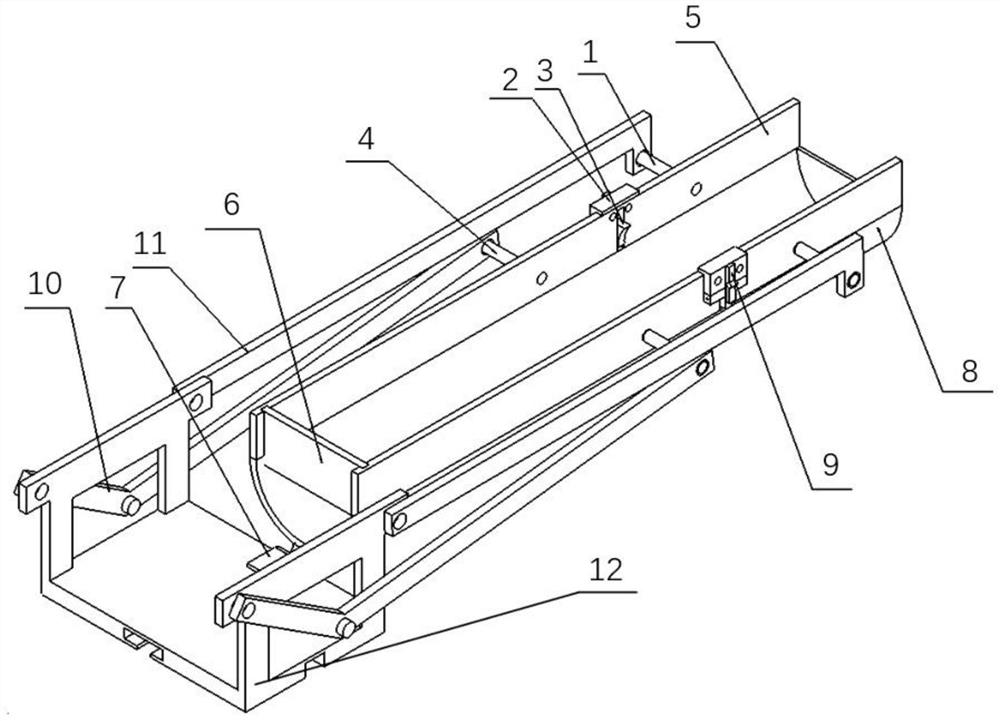
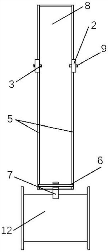
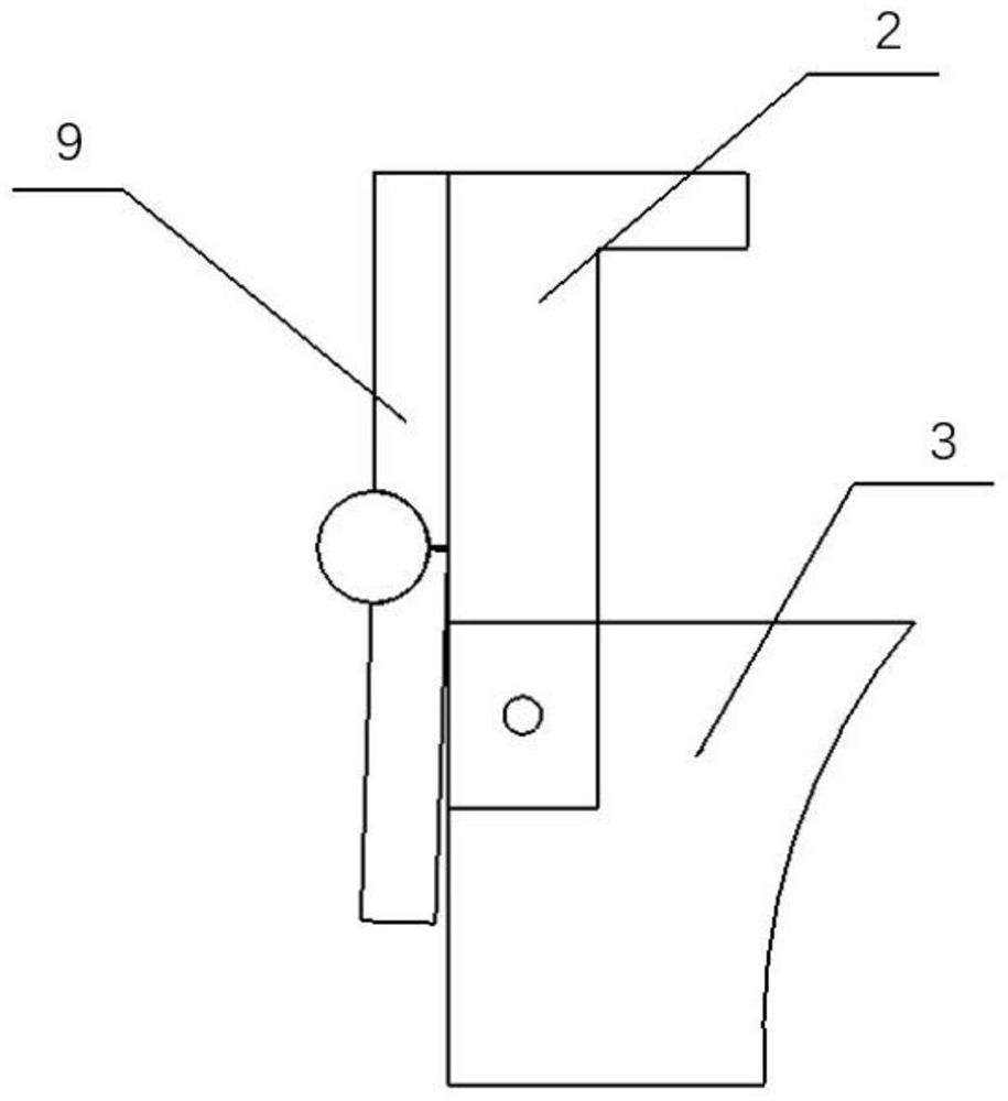
[0034] combine figure 1 In the present invention, the bomb support device used for automatic loading of projectiles includes a bomb support device arranged substantially parallel to the projectile launch tube (not shown in the figure) and a power actuator for operating the bomb support device to release the projectile body. The device includes a spring support base plate 8, two support side plates 5, a lateral limit block 3, a rotating block clip body 2, a torsion spring...


PUM


Abstract

The invention discloses a bomb support device for automatic loading of projectiles and a method for using the same. The bomb support device includes a bomb support arranged substantially parallel to the projectile launching cylinder and a power actuator for operating the bomb support to release the projectile. When in use, the bullet body is put into the bullet holder and is limited; the link mechanism of the power actuator drives the bullet holder to move downward, and the bullet retainer of the bullet holder is blocked by the releaser of the power actuator to move away from the bullet holder. When the bomb baffle moves to no longer in contact with the projectile, the projectile falls out of the bomb holder under the action of gravity and slides into the projectile launching tube to complete the loading of the projectile. The spring support device of the present invention does not adopt the full package limit commonly used in foreign automatic front loading technology, but adopts the point limit method in the upper limit, which saves the manufacturing cost, and the pure mechanical structure design has high safety and reliability, and is easier to load. Modified and upgraded to adapt to different types of ammunition.

Description

technical field [0001] The invention belongs to the technical field of projectile automatic loading, and in particular relates to a projectile supporting device for automatic projectile loading and a use method thereof. Background technique [0002] Mortar is an extremely important fire support weapon and plays an important role in the history of human warfare. Most mortars need to be manually loaded from the muzzle when in use. The projectile slides down by its own gravity and hits the firing pin at the bottom for firing. This loading method is prone to accidents such as repeated loading or reverse loading in actual use. When manually loading large-caliber mortar shells, due to the large volume and weight of the shells, it is difficult to manually load from the muzzle, the efficiency is low, and it is easy to fatigue the combatants and increase the danger. The automatic loading technology of mortars can solve the above problems well, but at present, most of the mechanisms ...

Claims


Application Information

Patent Timeline
Patent Type & Authority Patents(China)
IPC IPC(8): F41A9/38
CPCF41A9/38
Inventor 牛兆企马骏杰孙旺刘宁张相炎
Owner NANJING UNIV OF SCI & TECH
Why Eureka
Try Eureka