Optical fiber ribbon

A technology of optical fiber ribbon and optical fiber, applied in the direction of light guides, optics, optical components, etc., can solve problems such as inapplicability, and achieve the effect of preventing glue breaking

Inactive Publication Date: 2021-03-02
NANJING WASIN FUJIKURA OPTICAL COMM LTD +1
View PDF10 Cites 5 Cited by
  • Summary
  • Abstract
  • Description
  • Claims
  • Application Information

AI Technical Summary

Problems solved by technology

Existing optical cables are mainly cylindrical optical cables and flat optical fiber ribbons. Cylindrical optical cables are not suitable for flat gaps, and flat optical fiber ribbons are not suitable for smaller holes. If the optical fiber ribbons are forcibly bent, it will Causes a large fiber delay loss

Method used


Image

  • Optical fiber ribbon
  • Optical fiber ribbon
  • Optical fiber ribbon

Examples


Embodiment 1

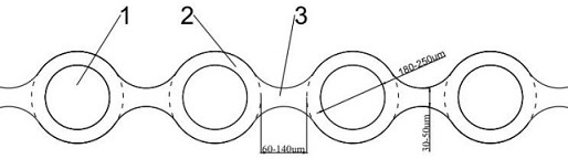
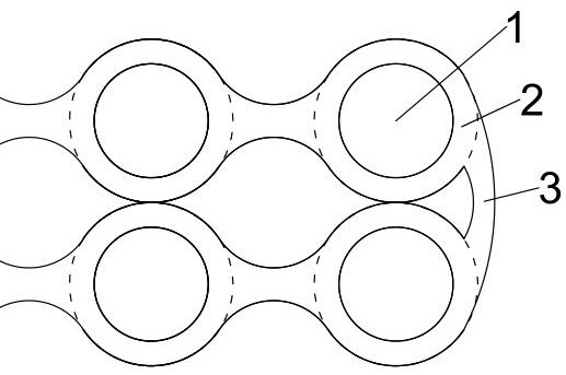
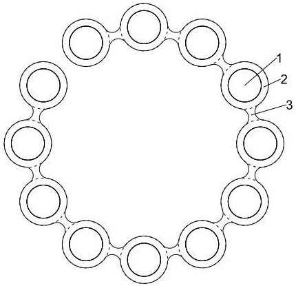
[0022] Such as figure 1 As shown, the optical fiber ribbon includes several optical fibers 1 and a cladding layer 2 covering the optical fibers. The optical fibers 1 pass through the mold cavity of a mold injected with resin to form the cladding layer 2 outside the optical fibers 1 .

[0023] The optical fiber ribbon of this embodiment also includes a connecting portion 3. In this embodiment, twelve optical fibers are taken as an example. The twelve optical fibers 1 are distributed along the linear direction with intervals, and each optical fiber 1 is covered by a coating layer 2 with uniform thickness. , the cladding layers 2 of adjacent optical fibers 1 are connected by the connecting part 3, so that both sides of the optical fiber ribbon along the length direction have a corrugated structure, and the thickness of the connecting part 3 is 1 / 3 to 1 / 2 of the diameter of the cladding layer 2, and Both the connecting part 3 and the cladding layer 2 are made of resin with a Young...

Embodiment 2

[0026] Such as Figure 4-6 As shown, this embodiment is a mold for producing optical fiber ribbons. The mold includes an inlet mold 4, a sizing mold 5 and an outlet mold 6 that fit together. The inlet mold 4, the sizing mold 5 and the outlet mold 6 are respectively provided with a number of connected entrance fiber holes 41 and sizing optical fibers. The hole 51 and the exit fiber hole 61 , this embodiment takes twelve entry fiber holes 41 , sizing fiber holes 51 and exit fiber holes 61 as an example.

[0027] The entrance fiber hole 41, the sizing fiber hole 51 and the exit fiber hole 61 are equally spaced, and the sizing fiber hole 51 aperture is smaller than the entrance fiber hole 41 and the exit fiber hole 61 aperture, which can effectively prevent two adjacent optical fibers 1 from When covering the rubber, the glue is broken at 3 places of the connecting part. The diameter of the entrance fiber hole 41 is 1.03-1.06 times that of the fixed-size fiber hole 51 , and the ...


PUM

PropertyMeasurementUnit
hardnessaaaaaaaaaa

Abstract

The invention relates to an optical fiber ribbon, which comprises a plurality of optical fibers and coating layers, the plurality of optical fibers form the coating layers outside the optical fibers through a mold cavity of a mold injected with resin, and the optical fiber ribbon further comprises connecting parts; the optical fibers are distributed at intervals in the linear direction, each optical fiber is coated with a coating layer with uniform thickness, the coating layers of the adjacent optical fibers are connected through the connecting parts, the two sides, in the length direction, ofthe optical fiber ribbon are of a corrugated structure, the thickness of the connecting parts is 1 / 3-1 / 2 of the diameter of the coating layers, and the connecting parts and the coating layers are made of resin with a Young modulus of 1Mpa-100Mpa, the optical fiber ribbon can be bent in the width direction through elastic deformation of the connecting parts. The connecting parts are soft, so thatthe optical fiber ribbon can be bent in the width direction, attenuation loss is avoided, and the optical fiber ribbon can be suitable for narrow gaps and small holes at the same time.

Description

technical field [0001] The invention relates to an optical cable, especially an optical fiber ribbon. Background technique [0002] Fiber optic cables are often used in narrow spaces such as holes. Existing optical cables are mainly cylindrical optical cables and flat optical fiber ribbons. Cylindrical optical cables are not suitable for flat gaps, and flat optical fiber ribbons are not suitable for smaller holes. If the optical fiber ribbons are forcibly bent, it will Cause greater fiber delay loss. Contents of the invention [0003] The object of the present invention is to overcome above-mentioned deficiencies in the prior art, provide a kind of optical fiber ribbon, comprise several optical fibers and cladding layer, several optical fibers form cladding layer outside optical fiber through the die cavity of the mold that is injected with resin, described optical fiber ribbon It also includes a connecting part; the plurality of optical fibers are distributed along the ...

Claims


Application Information

Patent Timeline
Patent Type & Authority Applications(China)
IPC IPC(8): G02B6/44B29C41/30B29C41/38
CPCG02B6/4403G02B6/443G02B6/4486B29C41/30B29C41/38
Inventor 王小泉张成龙杨飏刘骋李健
Owner NANJING WASIN FUJIKURA OPTICAL COMM LTD
Why Eureka
Try Eureka