Three-dimensional wiring design method for space optical remote sensor

A space optical remote sensing, three-dimensional wiring technology, applied in design optimization/simulation, instrumentation, calculation, etc., can solve the problems of late intervention, inapplicability, and not enough aesthetics in wiring design, so as to ensure data accuracy, optimize wiring design, design, etc. Efficient effect

Pending Publication Date: 2021-03-02
BEIJING RES INST OF SPATIAL MECHANICAL & ELECTRICAL TECH
View PDF0 Cites 0 Cited by
  • Summary
  • Abstract
  • Description
  • Claims
  • Application Information

AI Technical Summary

Problems solved by technology

[0005] (1) Since the wiring design of traditional optical remote sensors must rely on physical prototypes, this method is no longer applicable in the face of a one-step positive development model
[0006] (2) The wiring design is involved late, and the design of the routing path, turning radius, length and other aspects is completely dependent on experience for optimization. Most of the time, a large number of redundant designs are brought in to ensure reliability, resulting in insufficient optimization of the wiring design. not beautiful enough
[0007] (3) The design efficiency of large quantities of cables is low. The cable model must be attached to the structural design model. The 3D design model of the cable cannot be opened separately. It is difficult to extract design information, and it is impossible to generate a single cable engineering drawing. The subsequent reuse of the cable model Difficult to support the 3D design model to the factory
[0008] The platforms developed based on the two software environments of UG and Catia are not suitable for the three-dimensional wiring of remote sensors, because optical remote sensors are mainly carried out on the three-dimensional design platform based on PTC / ProE5.0, and cannot be replaced by UG and Catia platforms

Method used


Image

  • Three-dimensional wiring design method for space optical remote sensor
  • Three-dimensional wiring design method for space optical remote sensor

Examples


Embodiment Construction

[0028]Hereinafter, exemplary embodiments of the present disclosure will be described in more detail with reference to the accompanying drawings. Although the drawings show exemplary embodiments of the present disclosure, it should be understood that the present disclosure can be implemented in various forms and should not be limited by the embodiments set forth herein. On the contrary, these embodiments are provided to enable a more thorough understanding of the present disclosure and to fully convey the scope of the present disclosure to those skilled in the art. It should be noted that the embodiments of the present invention and the features in the embodiments can be combined with each other if there is no conflict. Hereinafter, the present invention will be described in detail with reference to the drawings and in conjunction with the embodiments.

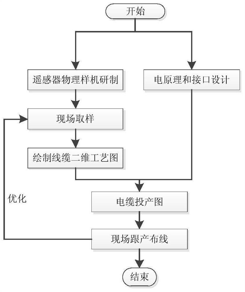
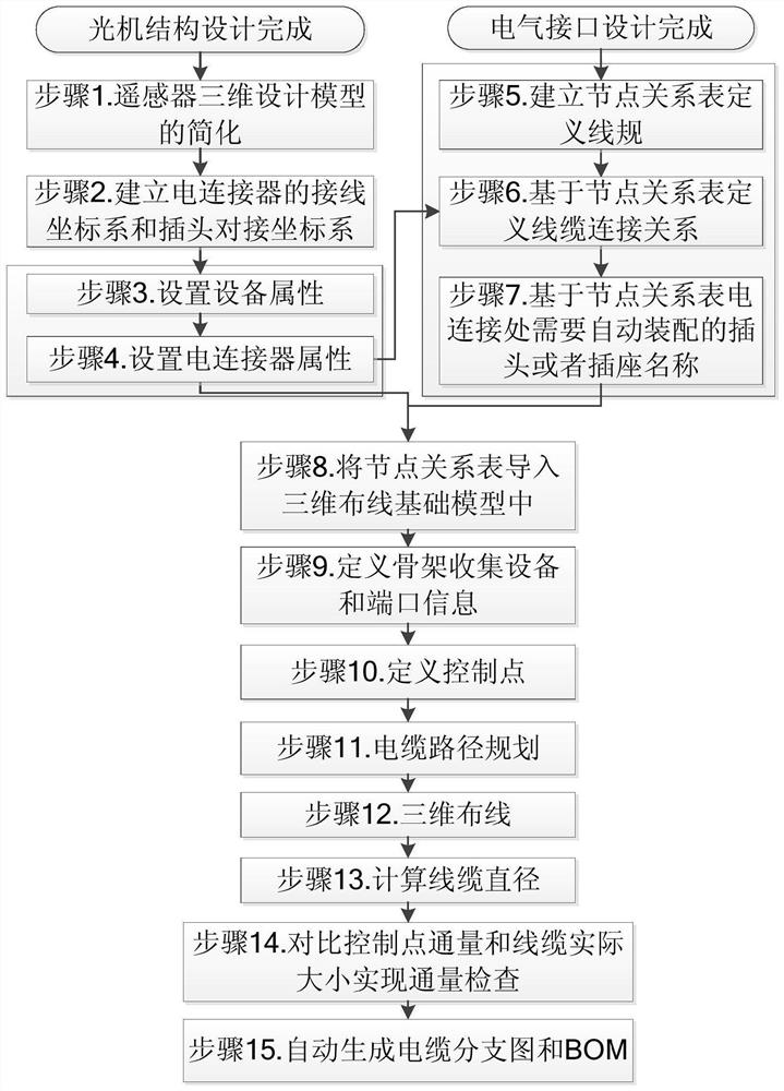
[0029]figure 2It is a flowchart of a three-dimensional wiring design method for a space optical remote sensor provided by an embodimen...


PUM


Abstract

The invention discloses a three-dimensional wiring design method for a space optical remote sensor, which can be used for wiring design based on a three-dimensional design model in a software environment with a version of PTC / ProeE5.0 and above. The method comprises the steps of simplifying the three-dimensional design model of the remote sensor and solving the problem of a large model; setting three-dimensional model electrical attributes of the equipment, the interface and the electrical connector, wherein the electrical attributes comprise an element code and an interface code; carding a contact relation table, wherein equipment and an electric connector in the table are kept consistent with those in the three-dimensional model; importing a contact relationship table, and establishing aone-to-one association relationship between the table and the model in the model; performing wiring design on the basis of any curved surface, and three-dimensional wiring path setting can be set intwo forms of control points or wire clamps; performing flux inspection of each control point or wire clip; and automatically generating a cable branch diagram and a wire report.

Description

Technical field[0001]The invention belongs to the technical field of wiring design for a space optical remote sensor, and in particular relates to a three-dimensional wiring design method for a space optical remote sensor.Background technique[0002]At present, the wiring design method of the space optical remote sensor is mainly two-dimensional expression, on-site follow-up production, sampling calculation on the physical prototype, combined with the electrical principle of the system to design the output interface relationship and put into production the cable processing drawing. The specific wiring design process is as followsfigure 1 Shown.[0003]In terms of the three-dimensional wiring design platform, there have been platforms developed in the two software environments of UG and Catia by the electric locomotive and the communications industry, and there is no wiring platform based on the PTC / ProE5.0 software environment.[0004]The problems with traditional wiring methods are as fo...

Claims


Application Information

Patent Timeline
IPC IPC(8): G06F30/20G06F30/18G06T17/00G06F16/28
CPCG06F30/20G06F30/18G06T17/00G06F16/284
Inventor 吴艳华裴永胜范慧莉练敏隆何鸿涛吴杰白邈刘丽玲
Owner BEIJING RES INST OF SPATIAL MECHANICAL & ELECTRICAL TECH
Why Eureka
Try Eureka