Row-shaped steel carding device

A profiled steel and row-by-row technology, which is applied in the field of rowed profiled steel carding devices in front of the straightening machine, can solve the problems of profiled steel misalignment, difficulty, and uneven size of horizontally arranged positions, and achieve the effect of high reliability and high degree of automation

Pending Publication Date: 2021-03-05
HUATIAN ENG & TECH CORP MCC
View PDF0 Cites 0 Cited by
  • Summary
  • Abstract
  • Description
  • Claims
  • Application Information

AI Technical Summary

Problems solved by technology

However, due to the inconsistency in the bending direction, position, and degree of the bending direction, position, and degree of the multiple steel sections to be fed on the roller table before straightening, and the unfavorable influence of factors such as uneven horizontal arrangement positions and sizes, under the conditions of the row straightening process, multiple steel sections in a row at the same time It is difficult to introduce the straightening machine, and it is easy to cause "dislocation" and "stacking" of the section steel before the leveling machine; the passability of the rows of section steel is reduced, which actually affects the operation efficiency of the row of straightening machines
Failure to properly address this issue will diminish the efficiency advantages of row straightening

Method used


Image

  • Row-shaped steel carding device
  • Row-shaped steel carding device
  • Row-shaped steel carding device

Examples


Embodiment Construction

[0022] The present invention will be further described below in conjunction with the accompanying drawings.

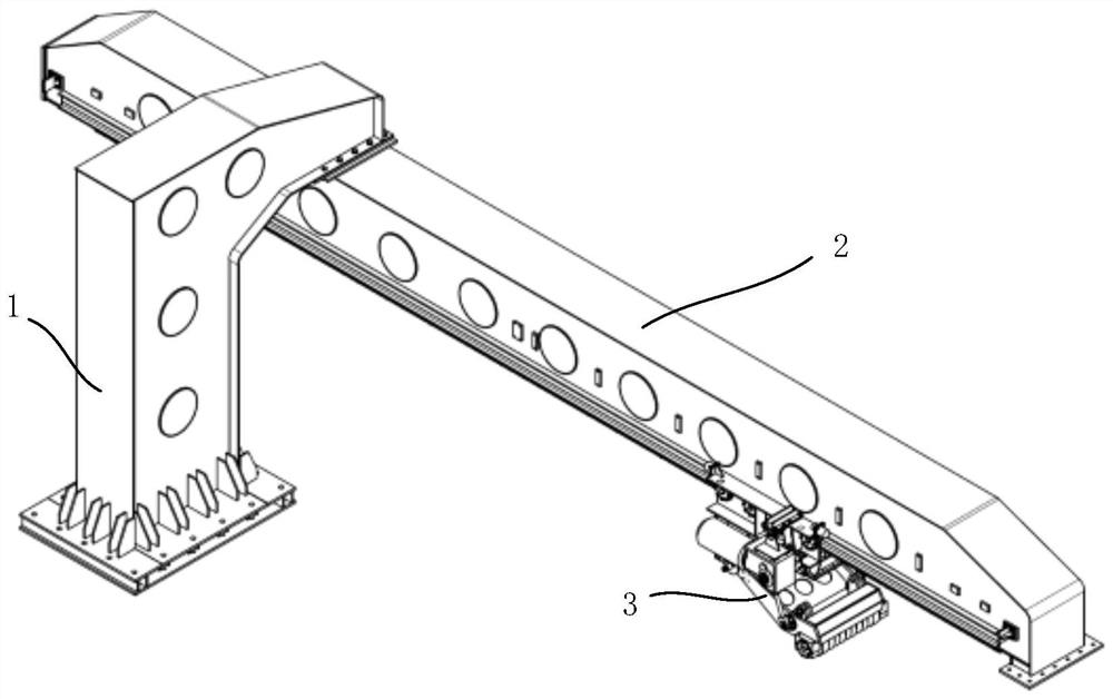
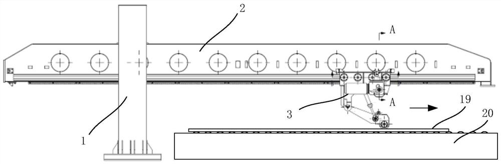
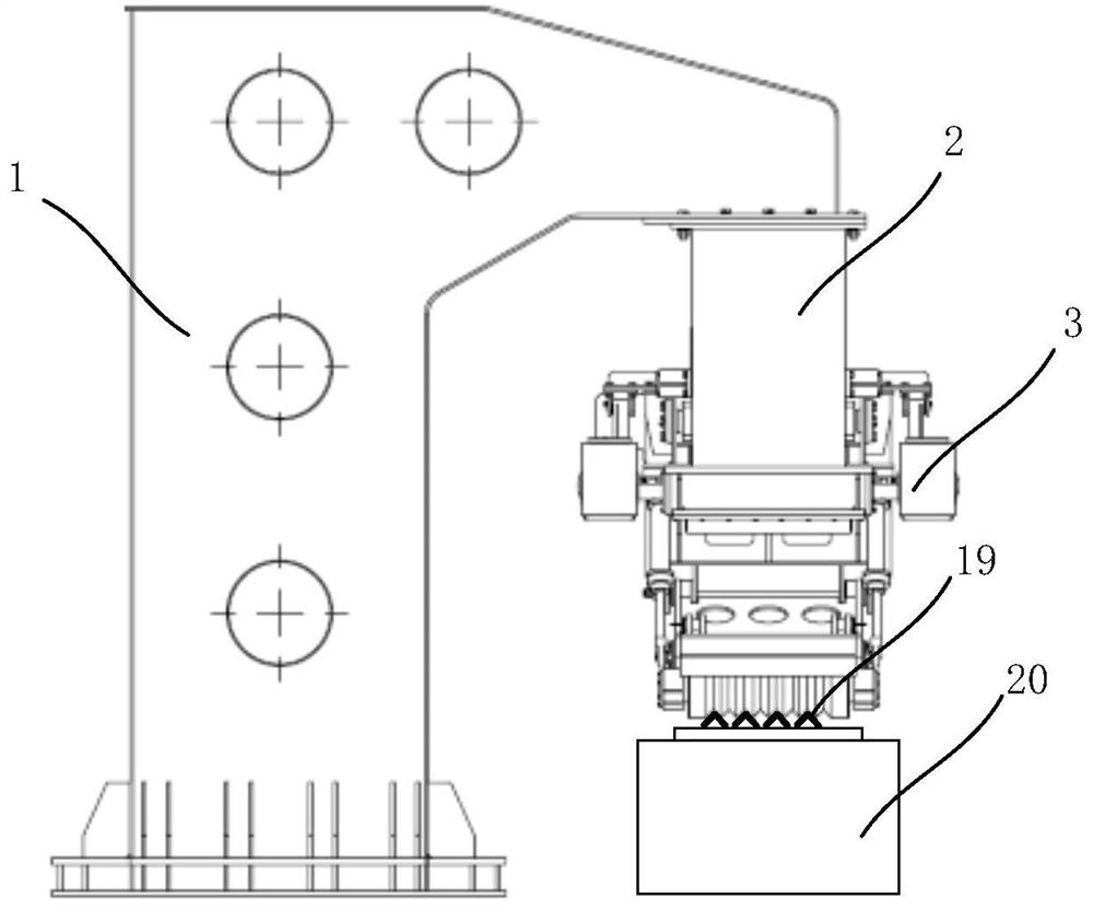
[0023] as attached Figures 1 to 10 As shown, a type steel carding device of the present invention includes: an inverted L-shaped column 1 , a beam 2 and a carding car 3 .

[0024] One end of the column 1 is arranged on the installation foundation, and the other end is connected with the beam 2;

[0025] The beam 2 includes a beam body 18, a first grooved guide rail 4, a second grooved guide rail 9, a first rack 6 and a second rack 10; the first grooved guide rail 4 and the second grooved guide rail 9 are arranged symmetrically On both sides of the beam body 18; the first rack 6 and the second rack 10 are arranged in parallel on the bottom surface of the beam body 18;

[0026] Described carding car 3 comprises: car body 13, guide wheel 5, first reduction motor 7, second reduction motor 11, gear shaft assembly 8, first oil cylinder 14, second oil cylinder 17, proximit...


PUM


Abstract

The invention discloses a row-shaped steel carding device. The row-shaped steel carding device comprises a stand column, a cross beam and a carding vehicle, wherein the cross beam comprises a cross beam body, a first groove-shaped guide rail, a second groove-shaped guide rail, a first rack and a second rack; the carding vehicle comprises a vehicle body, a guide wheel, a first gear motor, a secondgear motor, a gear shaft assembly, a first oil cylinder, a second oil cylinder, a proximity switch, a swing support and a carding roller assembly; one end of the stand column is arranged on an installation foundation, and the other end of the stand column is connected with the cross beam; the carding vehicle is connected with the cross beam through the guide wheel and a gear and rack pair; and thecarding vehicle can reciprocate along the cross beam under the drive of the motors, and the operation that row-shaped steel is carded at the same time through a carding roller is achieved. The row-shaped steel carding device is high in reliability and automation degree, and carding and alignment of multiple pieces of section steel running on a front roller way of a row straightening machine can be achieved so that the row straightening machine can smoothly bite the multiple pieces of section steel in rows.

Description

technical field [0001] The invention relates to a profiled steel carding device, in particular to a rowed profiled steel carding device in front of a straightening machine. Background technique [0002] The row leveling machine has the characteristic of synchronous straightening process of multiple steel profiles, which can increase the efficiency of the straightening process several times, thereby effectively increasing the production capacity of the steel profile production line. However, due to the inconsistency of the bending direction, position, and degree of the bending direction, position, and degree of the multiple steel sections to be fed on the roller table before straightening, and the unfavorable influence of factors such as uneven horizontal arrangement positions and sizes, under the conditions of the row straightening process, the row of multiple steel sections at the same time It is difficult to introduce the straightening machine, and it is easy to cause "dis...

Claims


Application Information

Patent Timeline
IPC IPC(8): B65G47/26B65G35/00B21D43/08
CPCB21D43/08B65G35/00B65G47/26
Inventor 卫卫方实年董岱石海军徐志坤潘天成
Owner HUATIAN ENG & TECH CORP MCC
Why Eureka
Try Eureka