
Bearing system

A bearing and shaft hole technology, applied in the direction of bearing components, shafts and bearings, rigid brackets of bearing components, etc., can solve the problems of unstable rotation of rotor 93 and noise, and achieve the effect of improving quality and reducing operating noise and vibration.

Inactive Publication Date: 2021-03-05
SUNONWEALTH ELECTRIC MACHINE IND
View PDF14 Cites 0 Cited by
  • Summary
  • Abstract
  • Description
  • Claims
  • Application Information

AI Technical Summary

Problems solved by technology

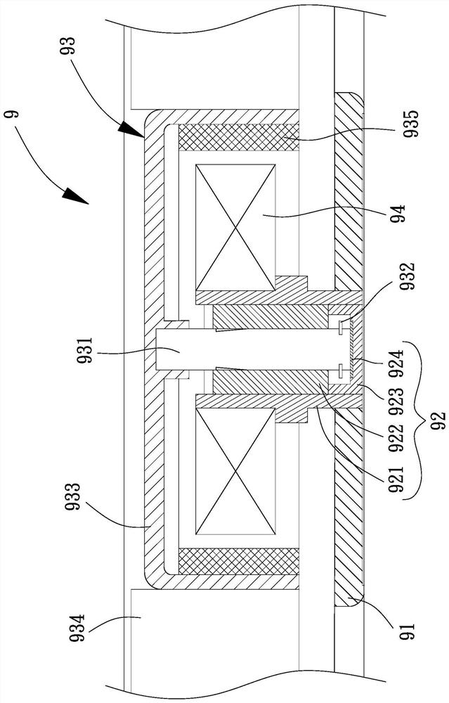
[0003] When the above-mentioned existing fan 9 is in operation, if the shaft rod 931 drifts upward, the axial displacement of the shaft rod 931 can be limited by the buckle plate 932 blocking the bottom end of the oil bearing 922; however, the buckle The plate 932 will repeatedly collide with the bottom end of the oil bearing 922, so that the rotation of the rotor 93 will be unstable due to vibration, and noise will also be generated at the same time

Method used


Image

  • Bearing system
  • Bearing system
  • Bearing system

Examples


no. 1 example

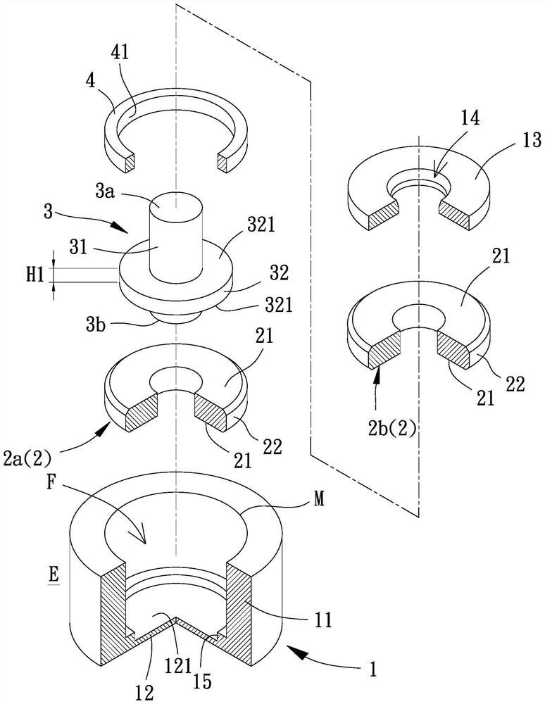
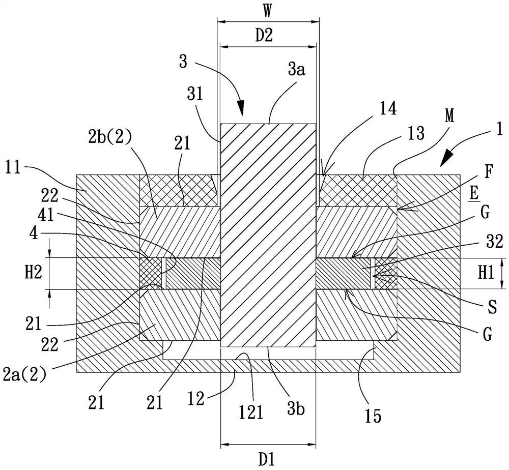
[0096] Please refer to figure 2 , 3 As shown, it is the first embodiment of the bearing system of the present invention, including a bushing 1, two bearings 2 and a rotating shaft 3, the two bearings 2 are located inside F of the bushing 1, and the rotating shaft 3 runs through the two A bearing 2 with one end protruding from the bush 1.

[0097] The bushing 1 has a ring wall 11 connected to the sealing bottom 12, so that the bottom end of the ring wall 11 is closed by the sealing part 12, and a space where the two bearings 2 can be arranged is formed inside the bushing 1 F. Wherein, the sealing portion 12 can be assembled and combined with the ring wall 11, for example, tightly fit and laser welded at the junction; The top end has an opening M, and the bottom end is completely closed to effectively prevent lubricating oil from leaking inside F of the bushing 1 . In addition, the bushing 1 can be provided with an end plate 13 adjacent to the opening M, the end plate 13 is ...


PUM


Abstract

A bearing system is used for solving the problem that an existing motor or fan is prone to generating vibration and noise due to collision of rotating components. The system comprises a lining which is communicated with the inside and the outside of the lining through a shaft hole; two bearings which are axially and oppositely located in the lining, and an interval space is formed between the twobearings; a rotating shaft which penetrates through the two bearings, the first end of the rotating shaft penetrates out of the shaft hole, the circumferential face of the rotating shaft is connectedwith an outwards-protruding part, the outwards-protruding part is located in the interval space, and a dynamic pressure gap can be formed between the outwards-protruding part and the axial end faces of the bearings when the rotating shaft rotates.

Description

technical field [0001] The invention relates to a component of a motor or a fan, in particular to a bearing system that can be installed in the motor or fan. Background technique [0002] Please refer to figure 1 , it is a kind of existing fan 9, and this existing fan 9 has a shaft seat 91, a bearing system 92, a rotor 93 and a stator 94. The bearing system 92 has a shaft cylinder 921 assembled on the shaft seat 91, an oil bearing 922 assembled inside the shaft cylinder 921, a sealing plug 923 to close the bottom of the shaft cylinder 921, and a wear pad 924 on the sealing Plug 923 inside. The rotor 93 has a shaft 931 passing through the oil bearing 922, the bottom end of the shaft 931 abuts against the wear-resistant pad 924, the outer peripheral surface of the shaft 931 is combined with a buckle 932, the buckle 932 is located on the oil bearing 922 Below, a hub 933 is connected to the top of the shaft 931 , a plurality of fan blades 934 are connected to the outer periph...

Claims


Application Information

Patent Timeline
Patent Type & Authority Applications(China)
IPC IPC(8): F16C35/02
CPCF16C35/02
Inventor 洪银树尹佐国李明聪
Owner SUNONWEALTH ELECTRIC MACHINE IND
Learn More