
Transformer

A transformer and device body technology, applied in the field of transformers, can solve problems such as unfavorable expansion and contraction of metal bellows, deviation and deformation of metal bellows, and insufficient technology, so as to facilitate heat dissipation, avoid thermal expansion damage, and avoid scratches Effect

Inactive Publication Date: 2021-03-05
张于标
View PDF5 Cites 0 Cited by
  • Summary
  • Abstract
  • Description
  • Claims
  • Application Information

AI Technical Summary

Problems solved by technology

[0002] Distribution transformers can be divided into oil-immersed transformers and dry-type transformers. As far as oil-immersed transformers are concerned, oil-immersed transformers are generally equipped with oil conservator. When the transformer oil heats up, the oil flows from the oil tank to the oil conservator. When the transformer oil When the oil shrinks, the oil flows from the oil conservator to the oil tank. When the transformer oil heats up, the oil flows from the oil tank to the oil conservator. The transformer oil that enters the oil conservator is hot oil. The pressure increases, which will easily lead to thermal expansion of the oil conservator, which will easily cause the oil conservator to burst for a long time, and for the metal corrugated oil conservator, because the technology is not perfect, the transformer oil in the oil conservator will exert force on the metal bellows , and the metal bellows has no supporting force, which will easily lead to the deviation and deformation of the metal bellows, which is not conducive to the expansion and contraction of the metal bellows

Method used


Image

  • Transformer
  • Transformer
  • Transformer

Examples


Embodiment 1

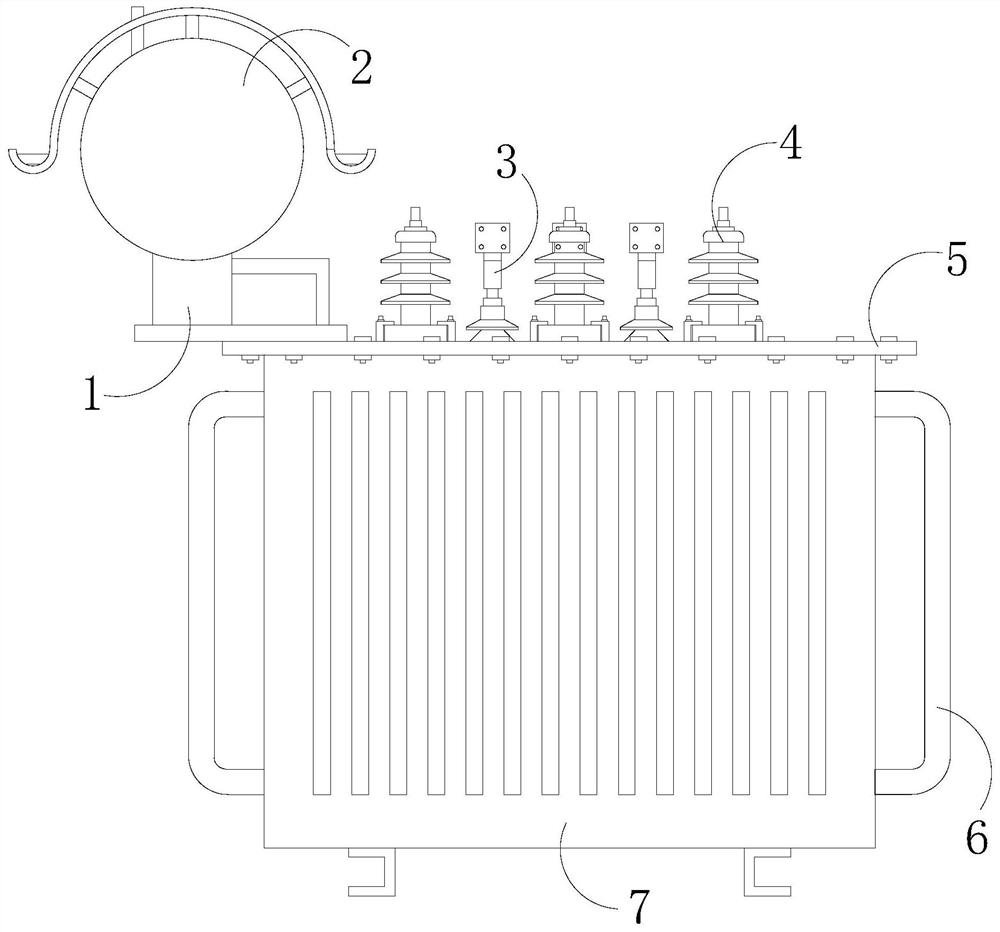
[0026] see Figure 1-6 , the present invention provides a technical scheme of a transformer: its structure includes a support frame 1, an oil conservator 2, a low-voltage bushing 3, a high-voltage bushing 4, a sealing cover 5, a heat dissipation pipe 6, and a body 7, and the body The front and both sides of 7 are connected with radiating pipes 6, and the top of the body 7 is connected with the sealing cover 5 through bolts and nuts, and the sealing cover 5 is equipped with a low-voltage bushing 3 and a high-voltage bushing 4, The low-voltage bushing 3 and the high-voltage bushing 4 are connected to the body 7 , and the body 7 is connected to the oil conservator 2 through the support frame 1 .

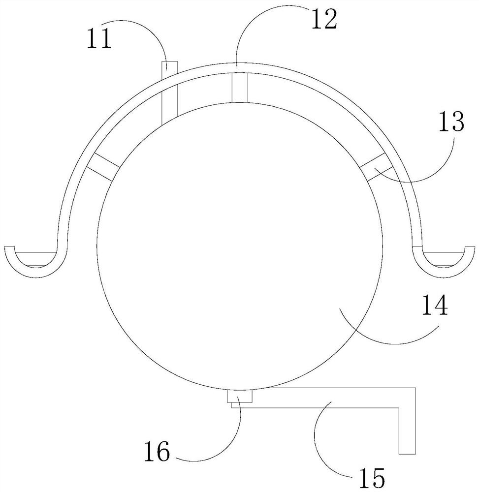
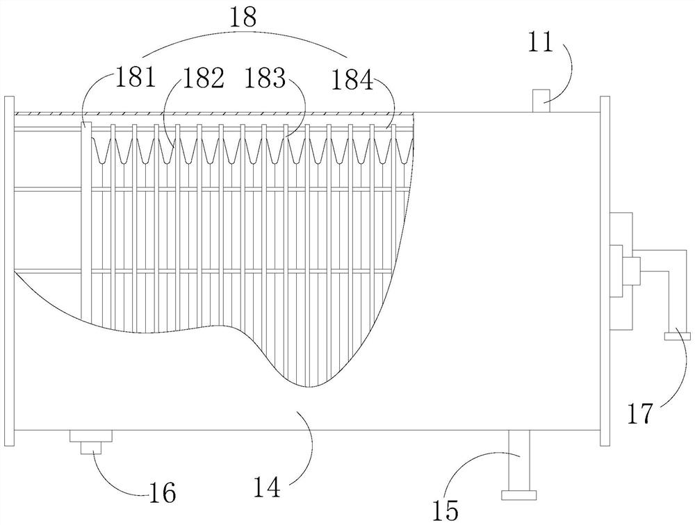
[0027] The oil conservator 2 includes an oil injection pipe 11, a heat shield 12, a connecting cylinder 13, an oil conservator body 14, an oil outlet pipe 15, a sewage pipe 16, an air pipe 17, and a metal bellows assembly 18. The top of the oil conservator body 14 The surface is connec...


PUM


Abstract

The invention discloses a transformer, and the transformer structurally comprises a supporting frame, an oil conservator, a low-voltage sleeve, a high-voltage sleeve, a sealing cover plate, heat dissipation pipes and a transformer body; the front face and the two side faces of the transformer body are connected with the heat dissipation pipes, and the top of the transformer body is connected withthe sealing cover plate through bolts and nuts. Compared with the prior art, the invention has the beneficial effects that the metal corrugated pipe can be prevented from deviating, deformation of themetal corrugated pipe due to the fact that transformer oil falls into a wave groove of the metal corrugated pipe or the transformer oil generates acting force on the metal corrugated pipe is avoided,and the situation that the quality of the transformer oil is affected due to metal chips generated by scraping can be avoided; the space can be increased by improving the connecting cylinder to contain hot air, so that the situation that the oil conservator body cracks due to too large pressure intensity is avoided, the heat insulation purpose is achieved by efficiently reflecting sunlight through the reflective heat insulation coating layer, and heat dissipation of the transformer oil is facilitated.

Description

technical field [0001] The invention relates to the technical field of transformers, in particular to a transformer. Background technique [0002] Distribution transformers can be divided into oil-immersed transformers and dry-type transformers. As far as oil-immersed transformers are concerned, oil-immersed transformers are generally equipped with oil conservator. When the transformer oil heats up, the oil flows from the oil tank to the oil conservator. When the transformer oil When the oil shrinks, the oil flows from the oil conservator to the oil tank. When the transformer oil heats up, the oil flows from the oil tank to the oil conservator. The transformer oil that enters the oil conservator is hot oil. The pressure increases, which will easily lead to thermal expansion of the oil conservator, which will easily cause the oil conservator to burst for a long time, and for the metal corrugated oil conservator, because the technology is not perfect, the transformer oil in th...

Claims


Application Information

Patent Timeline
Patent Type & Authority Applications(China)
IPC IPC(8): H01F27/02H01F27/06H01F27/14
CPCH01F27/022H01F27/025H01F27/06H01F27/14
Inventor 张于标
Owner 张于标
Learn More