
An operation safety protection device for power equipment

A technology for safe operation and protective devices, which is applied in the substation/distribution device enclosure, cooling/ventilation, transportation and packaging of substation/switchgear, etc. It can solve problems such as high manual maintenance costs, hindering air flow, and affecting heat dissipation effects , to achieve the effect of improving heat dissipation, reducing air flow, and reducing safety hazards

Active Publication Date: 2022-07-01
河南工学院
View PDF17 Cites 0 Cited by
  • Summary
  • Abstract
  • Description
  • Claims
  • Application Information

AI Technical Summary

Problems solved by technology

[0005] At that time, after a period of operation of the above-mentioned prior art, a large amount of dust would adhere to the vacuum net, hindering the air flow and affecting the heat dissipation effect. It was necessary to manually come to the site to clean the dust on the vacuum net regularly, which required high labor maintenance costs. In addition, power equipment generally needs to be powered off before opening the cabinet door to maintain the interior. In the prior art, the cabinet door can be opened when the power is on, which poses a safety hazard.
[0006] Therefore, it is necessary to design a kind of operation safety protection device for power equipment that can cool down the power equipment, automatically clean the dust, ensure the cooling effect, and cannot be opened under the power-on state, so as to reduce potential safety hazards to solve the current technical problems.

Method used


Image

  • An operation safety protection device for power equipment
  • An operation safety protection device for power equipment
  • An operation safety protection device for power equipment

Examples


Embodiment Construction

[0033] The specific embodiments of the present invention will be further described below with reference to the accompanying drawings and embodiments.

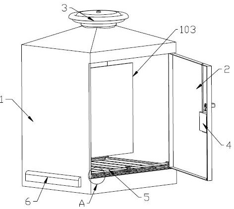
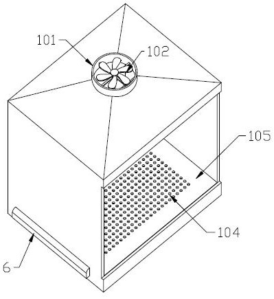
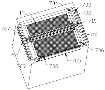
[0034] like Figures 1 to 3As shown, the operation safety protection device for electrical equipment includes a box body 1, a door panel 2 is hinged on the front side of the box body 1, and a power-on lock for locking or releasing between the door panel 2 and the box body 1 is arranged on the door panel 2. The power-on locking device 4 locks the door panel 2 and the box body 1 in the power-on state, and automatically releases the door panel 2 and the box body 1 after the power is turned off, so that the door panel can be opened, reducing safety. The top of the box body 1 is provided with an exhaust pipe 101 that communicates with it, the interior of the exhaust pipe 101 is provided with an induced draft fan 102, and the upper end of the exhaust pipe 101 is detachably installed with an exhaust mechanism 3; The interior of the b...


PUM


Abstract

The invention provides an operation safety protection device for electric equipment, comprising a box body, a door panel is hinged on the front side of the box body, and a power-on locking device for locking or releasing between the door panel and the box body is arranged on the door panel; The top of the body is provided with an exhaust pipe that communicates with it, the interior of the exhaust pipe is provided with an induced draft fan, and the upper end of the exhaust pipe is detachably installed with an exhaust mechanism; the interior of the box is divided into two upper and lower cavities by an orifice plate The bottom of the orifice plate is provided with a dust filter, and the top of the orifice plate is provided with a baffle mechanism; the box above the orifice plate is provided with a mounting plate, and the two sides of the box below the orifice plate are provided with air intake cavities. A dust removal mechanism is arranged inside the box body; in the present invention, the air flow inside the box body is driven by an induced draft fan, and the external air enters the bottom of the orifice plate in the box body from the air inlet cavity, and is filtered by the dust filter screen and discharged upwards by the exhaust mechanism. The air with a lower temperature outside the box is introduced into the box, which can play a role in cooling the power equipment.

Description

technical field [0001] The invention belongs to the technical field of electric equipment, and in particular relates to an operation safety protection device for electric equipment. Background technique [0002] The protection device of electrical equipment is a kind of equipment that protects the normal operation of electrical equipment. On the one hand, it can protect the normal operation of internal electrical facilities, and on the other hand, it can protect the personal safety of external personnel. [0003] At present, there are many dust particles in the environment where the general power equipment is located, and the accumulation of dust particles for a long time can easily cause damage to the power equipment. The power equipment is mainly manifested in low heat dissipation during use. If the heat emitted cannot be evacuated in time , causing the temperature rise to affect the stable operation of the power equipment. [0004] In the prior art, the Chinese utility m...

Claims


Application Information

Patent Timeline
Patent Type & Authority Patents(China)
IPC IPC(8): H02B1/46H02B1/28H02B1/56B01D46/681B01D46/10
CPCH02B1/46H02B1/28H02B1/565B01D46/10B01D46/681
Inventor 张雷李婕刘亚卓常文平王登银孙文乾孙克涛
Owner 河南工学院
Learn More