Manufacturing process of composite material battery box

A manufacturing process and composite material technology, which is applied to battery components, circuits, electrical components, etc., can solve the problems of restricting the application of metal bushing forming methods, increasing the size and weight of metal bushings, and low heating efficiency of materials. Achieve the effects of good product appearance, enhanced fluidity, and high process feasibility

Active Publication Date: 2021-03-09
许剑海
View PDF6 Cites 3 Cited by
  • Summary
  • Abstract
  • Description
  • Claims
  • Application Information

AI Technical Summary

Problems solved by technology

[0013] However, from the content disclosed in this patent, it can be known that: (1) Compared with the "preform direct transfer molding method", the material is directly in contact with the upper and lower high-temperature molds, and the metal bushing method has a metal bushing interlayer. The heating efficiency of the material during the molding process is lower; (2) Although the metal bushing greatly reduces the weight of the male mold, the metal bushing itself still has a certain weight, so it is necessary to use a mechanical arm to transfer it in and out of the mold
When the size of the battery box (battery case) product increases, the size and weight of the metal bushing will increase, and may exceed the handling weight and load range of automation equipment such as robotic arms, thus restricting the metal bushing forming method Application in the production of large-size battery box products

Method used


Image

  • Manufacturing process of composite material battery box
  • Manufacturing process of composite material battery box
  • Manufacturing process of composite material battery box

Examples


Embodiment Construction

[0055] In order to make the above-mentioned features and advantages of the present invention easier to understand, the following specific embodiments are described in detail with reference to the accompanying drawings, but the present invention is not limited thereto.

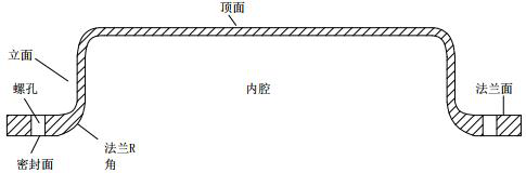
[0056] Generally, in order to meet the structural design requirements, the prepreg used in the PCM battery box can be designed with a large area of ​​large fabrics, surrounding flanges and flange thickening materials with thickened R angles, and reinforced R angles on the facade. materials, and other materials with structural design significance. Taking a PCM battery box with a flange thickness of about 2.5mm, a facade R angle thickness of about 1.6mm, and a thickness of the rest of the PCM battery box of about 0.9mm as an example, a prepreg sheet with a glass fiber area density of 400gsm and a resin content of about 40% is used. At this time, the large fabric is 3 layers of material, the flange thickening mate...


PUM

PropertyMeasurementUnit
thicknessaaaaaaaaaa
thicknessaaaaaaaaaa
thicknessaaaaaaaaaa

Abstract

The invention relates to a manufacturing process of a composite material battery box. The manufacturing process of the composite material battery box comprises the following steps of: manufacturing abattery box framework, wherein the battery box framework comprises peripheral flanges, and the inner side of each flange is connected with a vertical surface R corner part through a flange R corner part with gradually changed thickness; carrying out sand blasting treatment on the prepared battery box framework, and then cleaning and airing for later use; preparing a material spreading jig; spreading large fabric on the material spreading jig, and then placing the battery box framework into the material spreading jig and pressing the battery box framework; spreading the remaining large fabric on the battery box framework, and pressing again to form a battery box preform; transferring the material spreading jig on which the materials are spread into a low-temperature refrigerator to be refrigerated for 2 to 15 minutes; completing demolding of the preform, rapidly placing the preform into a high-temperature product mold, and conducting curing molding of the product; and after opening themold and carrying out post-processing, obtaining a final battery box finished product. The process is not limited by the size of the battery box product, and is high in feasibility, high in universality and high in production efficiency; and the occurrence of the phenomena of local material shortage cavitation, performance weakening and the like after the product is formed is avoided.

Description

technical field [0001] The invention relates to a manufacturing process of a composite material battery case. Background technique [0002] The battery box is the outer cover of the new energy vehicle power battery pack. It plays a role of waterproof, dustproof, support and insulation protection for the battery cells and accessory systems in the battery pack. It is one of the important components of the new energy vehicle. [0003] At present, new energy battery boxes are mainly divided into steel components (sheet metal parts), aluminum alloy parts and polymer composite components due to different needs. Among them, polymer composite components are favored by the new energy vehicle market because of their advantages such as light weight, high strength, large degree of freedom in structural design, simple and efficient molding process, and excellent shock absorption effect. [0004] PCM (Prepreg Compression Molding), namely (polymer composite material) prepreg molding proce...

Claims


Application Information

Patent Timeline
Patent Type & Authority Applications(China)
IPC IPC(8): B29C70/34B29C70/54H01M50/20H01M50/249B29L31/34
CPCB29C70/345B29C70/54B29L2031/7146Y02E60/10
Inventor 许剑海
Owner 许剑海
Why Eureka
Try Eureka