Automatic marking device for mouse shell

A technology for printing labels and casings, applied in the directions of printing devices, printing, printing machines, etc., can solve the problems of low printing efficiency, difficult mouse fixation, and easy offset of printing label positions, so as to improve the degree of automation and reduce labor intensity. Effect

Inactive Publication Date: 2021-03-09
胡涌域
View PDF16 Cites 2 Cited by
  • Summary
  • Abstract
  • Description
  • Claims
  • Application Information

AI Technical Summary

Problems solved by technology

[0004] In order to overcome the disadvantages that the mouse is not easy to fix, the marking position is easy to shift, and the printing efficiency is low, an automatic marking device for the mouse shell is provided with a high degree of automation, consistent marking positions, and high printing efficiency.

Method used


Image

  • Automatic marking device for mouse shell
  • Automatic marking device for mouse shell
  • Automatic marking device for mouse shell

Examples


Embodiment 1

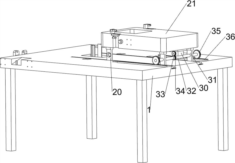
[0028] A kind of automatic marking device for mouse shell, such as figure 1 As shown, it includes a base 1 , a marking mechanism 2 and a moving mechanism 3 , the marking mechanism 2 is arranged on the top right side of the base 1 , and the moving mechanism 3 is arranged between the marking mechanism 2 and the base 1 .

[0029]The staff places the mouse on the designated position on the left side of the base 1, and then starts the moving mechanism 3 in the forward direction, and the moving mechanism 3 drives the marking mechanism 2 to move to a position close to the mouse, then stops the moving mechanism 3, and starts the marking mechanism 2 in the forward direction , the marking mechanism 2 prints the mouse shell, removes the mouse after the marking is completed, then reversely starts the marking mechanism 2, resets the marking mechanism 2, closes the marking mechanism 2 after resetting, and finally starts the moving mechanism in reverse 3. The moving mechanism 3 drives the ma...

Embodiment 2

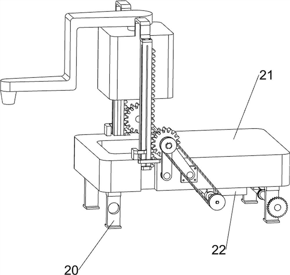
[0031] On the basis of Example 1, such as figure 2 , image 3 , Figure 4 and Figure 7 As shown, the marking mechanism 2 includes a first slider 20, a mounting table 21, a first servo motor 22, a first bearing seat 23, a first rotating shaft 24, a first bevel gear 25, a second bevel gear 26, a second bevel gear Bearing block 27, the first belt drive assembly 28, the first straight gear 29, the first tooth bar 210 and the mark table 211, base 1 top middle part sliding type is provided with a plurality of first slide blocks 20, the first slide block 20 and A mounting platform 21 is connected between the parts of the moving mechanism 3, the right part of the bottom of the mounting platform 21 is provided with a first servo motor 22, the bottom of the mounting platform 21 is symmetrically provided with a first bearing seat 23, and the first bearing seat 23 is connected with a first bearing seat 23. A rotating shaft 24, a first bevel gear 25 is connected to the output shaft of...

Embodiment 3

[0036] On the basis of Example 2, such as Figure 5 , Image 6 , Figure 7 , Figure 8 and Figure 9 As shown, a lifting mechanism 4 is also included. The bottom of the base 1 is provided with a lifting mechanism 4. The lifting mechanism 4 includes a first fixing assembly 40, a first spring 41, a third slider 42, a third rack 43, and a third bearing. Seat 44, third rotating shaft 45, fifth spur gear 46, second belt drive assembly 47, fourth bearing housing 48, fourth rotating shaft 49, sixth spur gear 410, fourth rack 411 and marking 412, base 1 The bottom is symmetrically provided with a first fixing component 40, and a third slider 42 is slidably connected to the first fixing component 40, and two first springs 41 are connected between the third slider 42 and the first fixing component 40, A third rack 43 is connected between the two third sliders 42, a third bearing seat 44 is connected to the middle part of the bottom of the base 1, a third shaft 45 is connected inside...


PUM


Abstract

The invention relates to a marking device, in particular to an automatic marking device for a mouse shell. The automatic marking device for the mouse shell is high in automation degree, consistent inmarking position and high in marking efficiency. The automatic marking device for the mouse shell comprises a base, a marking mechanism and a moving mechanism, wherein the base is used for mounting the whole device; the marking mechanism is arranged on one side of the top of the base; and the moving mechanism is arranged between the base and the marking mechanism. A second servo motor, a fourth straight gear and a first rack are matched, and forward rotation and reverse rotation of the second servo motor are manually controlled, so that the moving position of a marking table can be adjusted, and the marking table can conveniently mark the designated position of the mouse shell.

Description

technical field [0001] The invention relates to a marking device, in particular to an automatic marking device for a mouse shell. Background technique [0002] In the process of mouse processing and production, it is necessary to print patterns and logos on the surface of the mouse. However, due to the smooth shape of the mouse, it is not easy to fix the mouse, and the position of the printed mark is prone to shift, resulting in low quality and waste of products. The printed etching board is generally rigid, and it is more difficult for the mouse to carry out the roller embossing mark, and in the process of marking, as the mark is printed, the traces of the mark will become lighter and weaker, and the marking tool needs to be adjusted manually. Additional dipping and marking will increase the labor intensity of the staff and reduce the efficiency of marking. Therefore, the pad printing equipment widely used in the market is usually not highly automated, while the automation ...

Claims


Application Information

Patent Timeline
Patent Type & Authority Applications(China)
IPC IPC(8): B41F17/00G06F3/0354
CPCB41F17/00G06F3/03543B41P2217/50B41P2217/60
Inventor 胡涌域
Owner 胡涌域
Why Eureka
Try Eureka