Full-automatic hanging scaffold grabbing mechanism
A grasping mechanism, fully automatic technology, applied in the direction of conveyor objects, transportation and packaging, etc., can solve the problems of reduced work efficiency, easy to scratch, large space occupation, etc.
- Summary
- Abstract
- Description
- Claims
- Application Information
AI Technical Summary
Problems solved by technology
Method used
Image
Examples
Embodiment 1
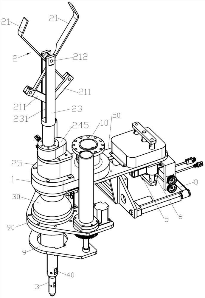
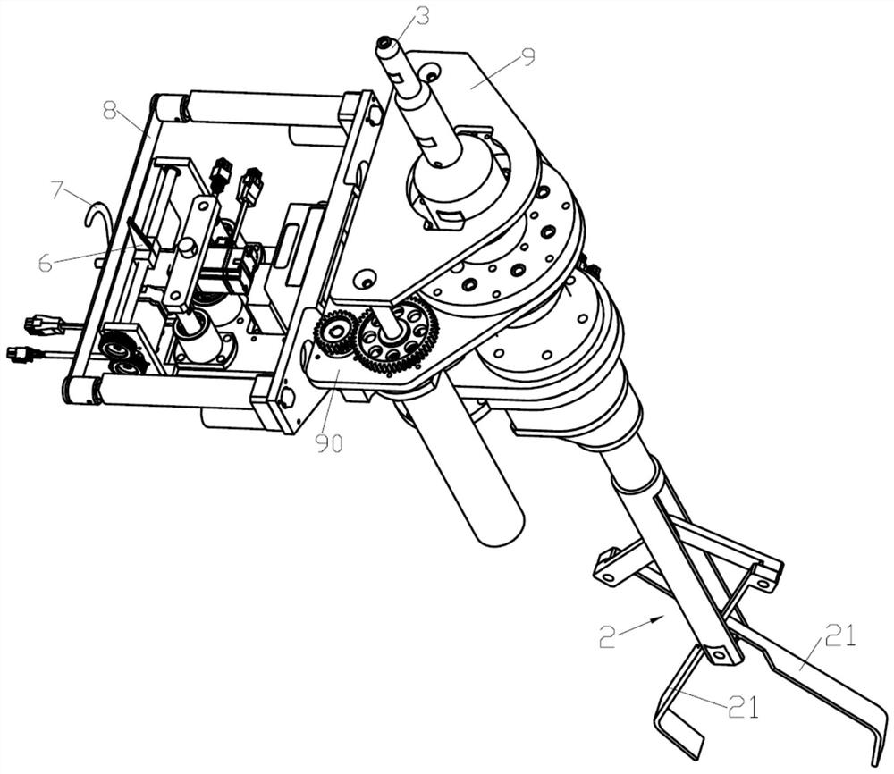
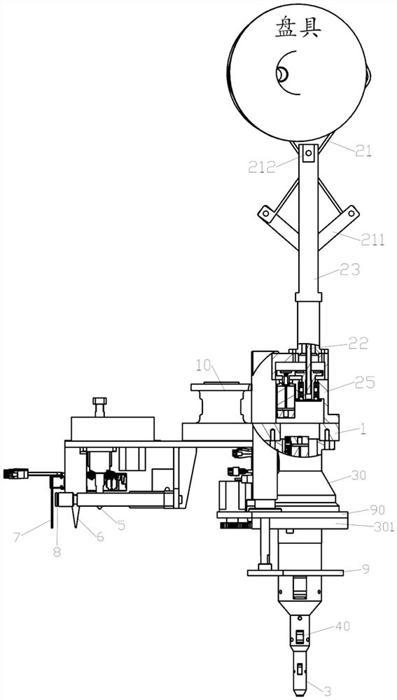
[0059] Such as Figures 1 to 3 As shown, a fully automatic hanging pan grabbing mechanism according to an embodiment of the present invention includes a base 1, a thread end processing device located at one end of the base 2, and a lifting device located at the other end of the base 1. The seat 1 is provided with a manipulator positioning ring 10, and one side of the manipulator positioning ring 10 is provided with a grasping device 2, and the grasping device 2 includes a jaw plate 21 capable of grabbing a dish, and the manipulator positioning ring 10 is used for connecting the manipulator to realize the The overall flip and movement of the automatic hanging pan grabbing mechanism. The empty plate is grabbed by the jaw plate 21. The manipulator drives the automatic hanging plate grabbing mechanism to turn over 90 degrees as a whole, so that the plate is placed upright, so that the thread end processing device is close to the full plate. To prevent the thread ends and thread t...
Embodiment 2
[0083] Such as Figures 27 to 29 As shown, the main difference between the fully automatic hanging pan grabbing mechanism described in Embodiment 2 and Embodiment 1 is that the gripper driving device 24 that drives the gripper rod shaft 22 and the control shaft driver 44 that drives the control shaft 4 , the lifting structure of the drive plate tool pressing plate 9, the off-line driving parts that drive the off-line top 5 are different. In this embodiment, pneumatic control is mainly used.
[0084] Such as Figure 27 As shown, the jaw driving device 24 adopts a cylinder 24B, and the cylinder body of the cylinder 24B is fixedly installed on the gripper seat 25, and the piston rod of the cylinder 24B passes through the gripper seat 25 and is connected with the gripper rod shaft 22. When the cylinder 24B is used as the jaw driving device 24, the piston rod of the cylinder 24B is used to control the jaw rod shaft 22 to move forward or backward. When the jaw rod shaft 22 moves ...
PUM
 Abstract
Description
Claims
Application Information
 - R&D
- Intellectual Property
- Life Sciences
- Materials
- Tech Scout
- Unparalleled Data Quality
- Higher Quality Content
- 60% Fewer Hallucinations
Browse by: Latest US Patents, China's latest patents, Technical Efficacy Thesaurus, Application Domain, Technology Topic, Popular Technical Reports.
© 2025 PatSnap. All rights reserved.Legal|Privacy policy|Modern Slavery Act Transparency Statement|Sitemap|About US| Contact US: help@patsnap.com


