Automobile exhaust pipe with refrigerating and cooling function

A technology for exhaust pipes and automobiles, which is applied in the direction of exhaust devices, mechanical equipment, engine components, etc. It can solve the problems of rising exhaust pipes, affecting people's normal life, and affecting the service life of exhaust pipes, so as to increase the amount of pumped water. big effect

Inactive Publication Date: 2021-03-09
德清县高桥绢纺厂
View PDF6 Cites 5 Cited by
  • Summary
  • Abstract
  • Description
  • Claims
  • Application Information

AI Technical Summary

Problems solved by technology

[0003] Due to the high temperature in the automobile exhaust, the temperature of the exhaust pipe will be too high when the automobile exhaust flows in the exhaust pipe, and then when the car is driving for a long time, the temperature on the exhaust pipe will rise sharply, affectin

Method used


Image

  • Automobile exhaust pipe with refrigerating and cooling function
  • Automobile exhaust pipe with refrigerating and cooling function

Examples


Embodiment 1

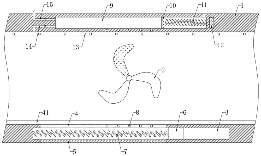
[0022] refer to figure 1 , an automobile exhaust pipe with cooling and cooling functions, comprising a pipe body 1, the inner wall of the pipe body 1 is connected with a plurality of impellers 2 through rotating shafts, the inner wall of the pipe body 1 is uniformly provided with a plurality of heat-absorbing cavities 3, and a plurality of The inner wall of the heat-absorbing chamber 3 is fixedly connected with the first conductive plate 4 communicating with the inner wall of the pipe body 1, the inner wall of the pipe body 1 is fixedly connected with the heat-absorbing plate 41 in contact with the first conductive plate 4, and the inner walls of the multiple heat-absorbing chambers 3 are fixedly connected There is a second conductive plate 5 communicating with the side wall of the pipe body 1 , a conductive block 6 is slidably connected in the heat-absorbing chamber 3 , and the side wall of the conductive block 6 is elastically connected to the inner wall of the heat-absorbing...

Embodiment 2

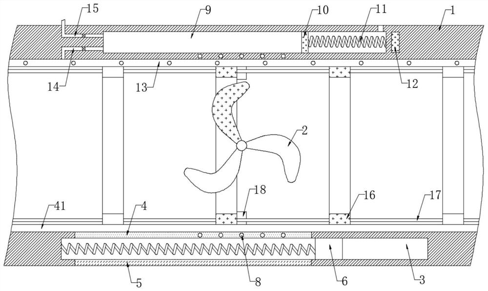
[0031] refer to figure 2, the difference from the first embodiment is that the inner wall of the pipe body 1 is slidingly connected with a plurality of scraper rings 16, and the plurality of scraper rings 16 are fixedly connected by a fixed rod 17, and the two scraper rings 16 close to the impeller 2 are made of magnetic materials The inner wall of the pipe body 1 is located at the axis of the impeller 2 and is fixedly connected with two partitions 18 symmetrically.

[0032] In this embodiment, the rotation of the impeller 2 makes the impeller 2 made of magnetic material alternately close to the two adjacent scraper rings 16, so that the scraper ring 16 drives the rest of the scraper rings 16 through the fixed rod 17 under the action of the magnetic attraction force of the impeller 2. A plurality of scraper rings 16 slide on the inner wall of the pipe body 1 to scrape off impurities in the pipe body 1 to avoid blockage of the pipe body 1 caused by carbon deposits in the pipe ...


PUM


Abstract

The invention discloses an automobile exhaust pipe with the refrigerating and cooling function. The automobile exhaust pipe comprises a pipe body, a plurality of impellers are rotatably connected to the inner wall of the pipe body through a rotating shaft, a plurality of heat absorption cavities are evenly formed in the inner wall of the pipe body, and first conductive plates communicating with the inner wall of the pipe body are fixedly connected to the inner walls of the multiple heat absorption cavities; and second conductive plates communicating with the side wall of the pipe body are fixedly connected to the inner walls of the multiple heat absorption cavities, conductive blocks are slidably connected into the heat absorption cavities, and the side walls of the conductive blocks are elastically connected with the inner walls of the heat absorption cavities through conductive springs. When circuits between the first conductive plates and the second conductive plates are conducted,a Peltier effect occurs, so that the first conductive plates serve as heat absorption ends, the second conductive plates serve as heat release ends, continuous heat absorption is performed on the interior of the pipe body, the temperature in the pipe body and the temperature in tail gas are reduced, the service life of the pipe body is prolonged, and meanwhile, the greenhouse effect is reduced.

Description

technical field [0001] The invention relates to the technical field of exhaust pipes, in particular to an automobile exhaust pipe with cooling and cooling functions. Background technique [0002] The automobile exhaust pipe is installed in the exhaust pipe between the engine exhaust branch pipe and the muffler, so that the entire exhaust system is flexibly connected, thereby reducing vibration and noise, facilitating installation and prolonging the life of the exhaust muffler system . [0003] Due to the high temperature in the automobile exhaust, the temperature of the exhaust pipe will be too high when the automobile exhaust flows in the exhaust pipe, and then when the car is driving for a long time, the temperature on the exhaust pipe will rise sharply, affecting the exhaust gas. The service life of the trachea, in addition, the high temperature exhaust gas will produce a greenhouse effect when discharged, and the automobile exhaust contains a large amount of harmful sub...

Claims


Application Information

Patent Timeline
IPC IPC(8): F01N3/02F01N3/04F01N5/04F01N13/08F02B77/04
CPCF01N3/02F01N3/04F01N5/04F01N13/08F02B77/04Y02T10/12
Inventor 沈超锋
Owner 德清县高桥绢纺厂
Why Eureka
Try Eureka