A liquid inlet device for a shunt body and its method and application

A liquid inlet device and branching technology, applied in the direction of mechanical equipment, etc., can solve the problem of uneven distribution of refrigerant, achieve the effect of improving distribution uniformity, flow noise and flow pressure drop, and improving phase separation

Active Publication Date: 2022-02-11
NINGBO AUX ELECTRIC
View PDF6 Cites 0 Cited by
  • Summary
  • Abstract
  • Description
  • Claims
  • Application Information

AI Technical Summary

Problems solved by technology

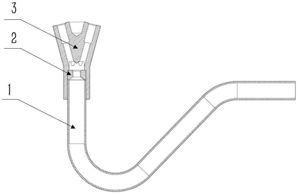
[0004] The technical problem to be solved by the present invention is to provide a shunt body liquid inlet device and its method and application in view of the above-mentioned deficiencies in the prior art, so as to solve the problems caused by the refrigerant phase separation phenomenon in the existing shunt body liquid inlet pipe. The problem of uneven distribution of refrigerant

Method used


Image

  • A liquid inlet device for a shunt body and its method and application
  • A liquid inlet device for a shunt body and its method and application
  • A liquid inlet device for a shunt body and its method and application

Examples


Embodiment Construction

[0035] In describing the present invention, it should be understood that the terms "center", "longitudinal", "transverse", "upper", "lower", "front", "rear", "left", "right", " The orientation or positional relationship indicated by "vertical", "horizontal", "top", "bottom", "inner", "outer", "side", "end", "side" etc. is based on the Orientation or positional relationship is only for the convenience of describing the present invention and simplifying the description, and does not indicate or imply that the referred device or element must have a specific orientation, be constructed and operated in a specific orientation, and thus should not be construed as a limitation of the present invention. In addition, the terms "first" and "second" are used for descriptive purposes only, and cannot be interpreted as indicating or implying relative importance or implicitly specifying the quantity of indicated technical features. Thus, a feature defined as "first" and "second" may explicit...


PUM


Abstract

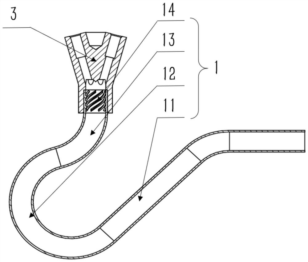
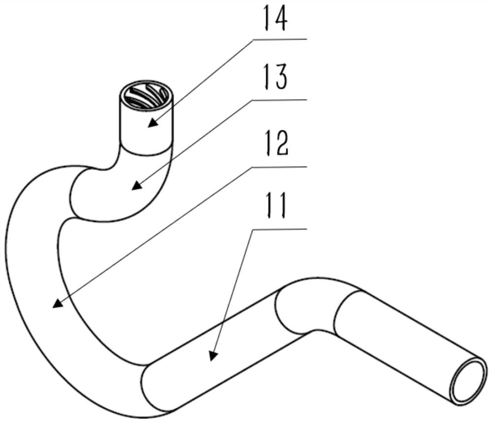
The invention discloses a liquid inlet device for a shunt body and its method and application. The outlet of the liquid inlet device is connected with the shunt body, including a front bend pipe section, a first bend pipe, a second bend pipe and an internal thread connected in sequence. Section, the turning direction of the second elbow is opposite to that of the first elbow, and the end of the second elbow is connected to the internal threaded pipe. The invention improves the phase separation phenomenon caused by the liquid inlet pipe elbow through the phase separation phenomenon of the reverse elbow and the internal thread balance elbow, so that the gas-liquid two-phase refrigerant enters the branch body evenly, and improves the distribution uniformity of the branch body. At the same time, the flow noise in the shunt body is small.

Description

technical field [0001] The invention belongs to the technical field of air conditioning, and in particular relates to a liquid inlet device for a shunt body and its method and application. Background technique [0002] In order to reduce the pressure loss in the air conditioner evaporator, the refrigerant needs to be divided into multiple branches. The branch body is installed between the expansion valve and the evaporator, and its function is to equally distribute the two-phase refrigerant throttled by the expansion valve into the capillary tubes of each branch and enter the evaporator. There is usually a section of liquid inlet pipe at the inlet of the branch body to send the refrigerant into the branch body. [0003] Under normal circumstances, due to the limitation of the internal space of the air conditioner, the installation position of the branch body is lower, and the liquid inlet pipe of the branch body needs to be turned by more than 90° to be inserted into the br...

Claims


Application Information

Patent Timeline
Patent Type & Authority Patents(China)
IPC IPC(8): F25B41/40
Inventor 蒲亮念洛竹张德润
Owner NINGBO AUX ELECTRIC
Why Eureka
Try Eureka