Flap valve head loss experiment testing system and using method thereof

A testing system and water head technology, which is applied in the direction of mechanical valve testing, etc., can solve the problems of inaccurate calculation of water head loss coefficient and complicated water flow movement at the valve outlet, so as to improve the accuracy and efficiency of experiments, facilitate movement and assembly Effect

Active Publication Date: 2021-03-09
YANGZHOU UNIV
View PDF9 Cites 0 Cited by
  • Summary
  • Abstract
  • Description
  • Claims
  • Application Information

AI Technical Summary

Problems solved by technology

The design of the flap door, the hydraulic calculation of the outlet flow channel and the determination of the working point of the pump device all need to know the head loss coefficient of the flap door. There are several types of flap doors, such as single-beat doors and double-beat doors. Each type is due to the structure Different and different forms, especially for double-beat doors, because the opening angles of the upper and lower doors are not consistent during operation, there is an angle difference, and double-beat doors can have different size ratios between upper and lower doors, As a result, the water flow movement at the outlet of the valve is quite complicated, and the head loss coefficient cannot be accurately calculated in engineering design calculations.

Method used


Image

  • Flap valve head loss experiment testing system and using method thereof
  • Flap valve head loss experiment testing system and using method thereof
  • Flap valve head loss experiment testing system and using method thereof

Examples


Embodiment Construction

[0048] The present invention will be described in further detail below in conjunction with the accompanying drawings.

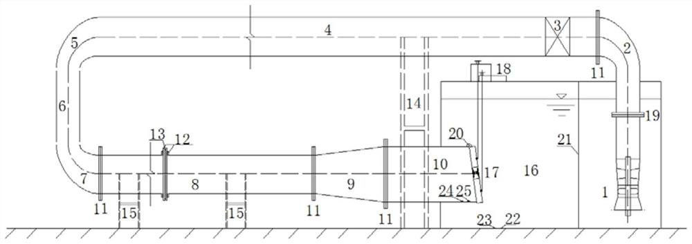
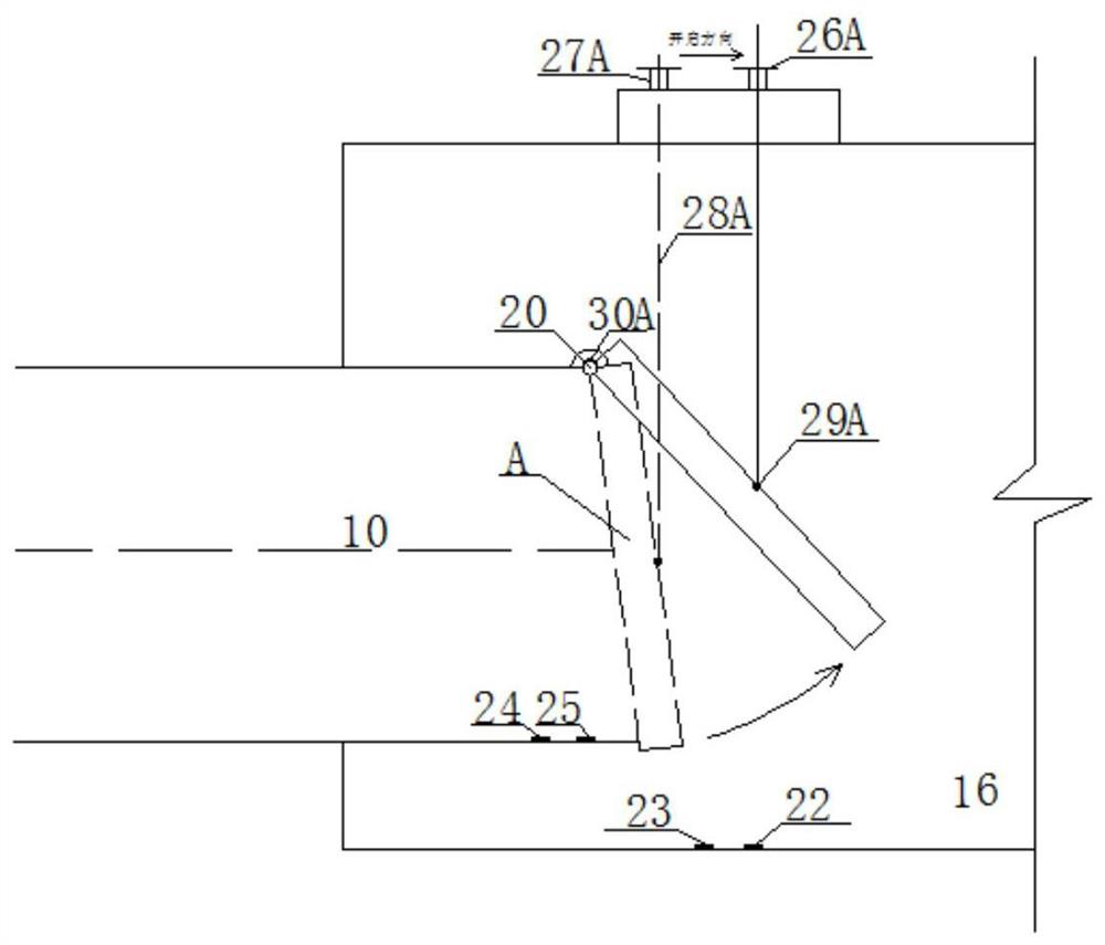
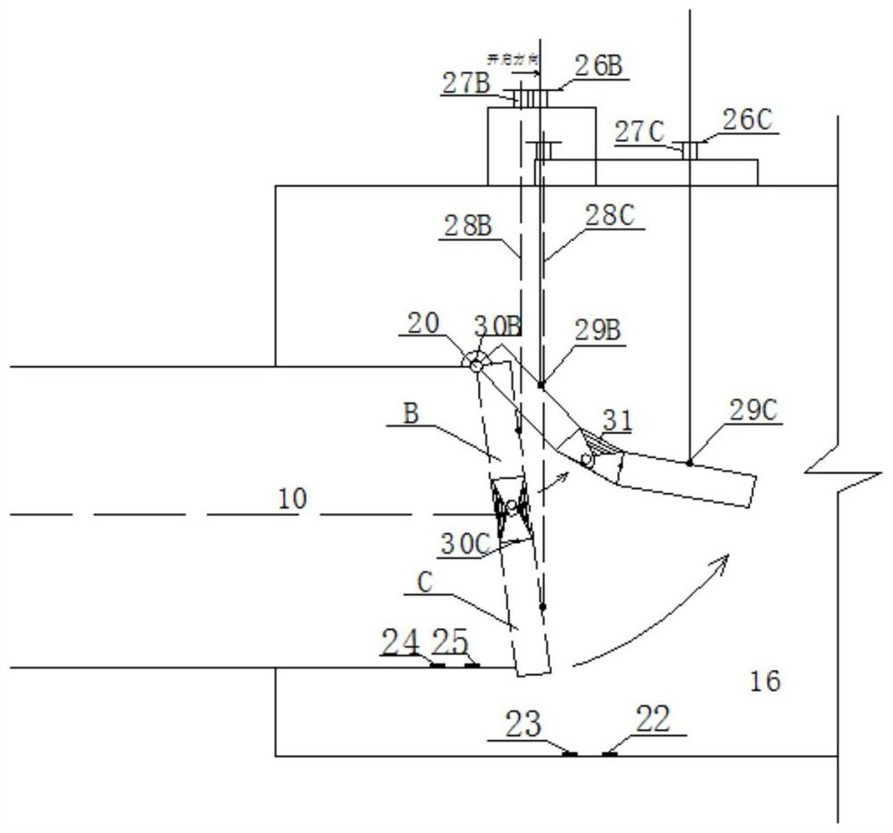
[0049] Such as Figure 1 to Figure 7 As shown, a kind of valve head loss experimental testing system and its using method of the present invention comprise:

[0050] Single beat gate A, upper beat gate B of double beat gates, lower beat gate C of double beat gates, cross-flow submersible pump 1, PVC right-angle diffusion elbow Ⅰ 2, control gate valve 3, PVC horizontal straight pipe 4, PVC Right-angle shrinking elbow 5, PVC vertical straight pipe 6, PVC right-angle diffuser elbow II 7, organic glass horizontal straight tube 8, organic glass gradient tube 9, transparent plastic tube 10, steady flow plate 11, pressure measuring hole 12, standard hole Plate 13, "H" type fixed bracket Ⅰ14, "H" type fixed bracket II 15, transparent plastic box 16, flap door body 17, flap door opening angle control device 18, expansion joint 19, rigid door shaft 20, flow barrier 2...


PUM


Abstract

The invention discloses a flap valve head loss experiment testing system and a using method thereof. The testing system comprises a pipeline, a pipeline supporting structure, a flap valve opening angle control device, a transparent plastic box and a testing subsystem, wherein the pipeline is formed by sequentially connecting a cross-flow submersible electric pump, a PVC right-angle diffusion elbowI, a regulating gate valve, a PVC horizontal straight pipe, a PVC right-angle contraction elbow, a PVC vertical straight pipe, a PVC right-angle diffusion elbow II, an organic glass horizontal straight pipe, an organic glass gradual change pipe and a transparent plastic pipe. The tail end of the transparent plastic pipe is arranged in the transparent plastic box, the cross-flow submersible electric pump is located in the transparent plastic box, the flap valve body to be tested is connected to the upper portion of the tail end of the transparent plastic pipe in a hinged mode, and the testingsubsystem is used for testing and collecting data. The specification and size of the model flow channel can be adjusted through the design of the transition section, the turning section and other pipesections; the water head losses of the flap valves of different types and specifications and sizes under different opening degrees can be measured by changing the arrangement type, size and opening angle of the flap valves.

Description

technical field [0001] The invention belongs to the field of water conservancy and mechanical engineering, and in particular relates to an experimental testing system for water head loss of a flapper door and a use method thereof. Background technique [0002] When flap gates are used as shut-off measures for pumping stations, engineers and technicians are mainly concerned about the opening angle and head loss of flap gates during the design and operation of flap gates, as well as the impact force of flap gates and building safety when shutting down. The design of the flap, the hydraulic calculation of the outlet flow channel, and the determination of the working point of the pump device all need to know the head loss coefficient of the flap, and there are several types of flaps, such as single-beat and double-beat. Different and different forms, especially for double-beat doors, because the opening angles of the upper and lower doors are not consistent during operation, the...

Claims


Application Information

Patent Timeline
IPC IPC(8): G01M13/003
CPCG01M13/003Y02E30/30
Inventor 徐波刘健峰陆伟刚陆林广徐磊陈华
Owner YANGZHOU UNIV
Why Eureka
Try Eureka