

Method for establishing Hamiltonian model of diesel generating set
A technology for diesel generator sets and building methods, used in complex mathematical operations, geometric CAD, design optimization/simulation, etc.
- Summary
- Abstract
- Description
- Claims
- Application Information
AI Technical Summary
Problems solved by technology
Method used
Image


Examples
Embodiment 1
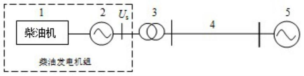
[0065] A method for establishing a Hamiltonian model of a diesel generating set, wherein the diesel generating set includes a diesel engine and a generator, comprising the following steps:
[0066] Step 1: Establish the Lagrangian function of the diesel engine:
[0067] (1) The establishment process of the actuator Lagrangian model:
[0068] The actuator is the actuator of the diesel engine to the external control signal, through which the control of the diesel engine is realized, and all types of diesel actuators are the same after being abstracted into mathematical models.
[0069] Assuming that the input signal of the electromagnetic actuator of the diesel engine is u, the displacement of the output shaft is x, the electromagnetic force F generated by the armature movement on the shaft can be expressed as F(x,u), assuming that the initial actuator works at the input signal u 0 , the displacement is x 0 The steady state of , then the electromagnetic force can be expressed ...
Embodiment 2
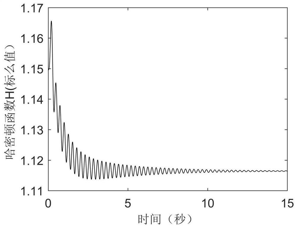
[0138] In order to verify the correctness of the Hamiltonian function in Embodiment 1, simulation is carried out from two aspects, (1) the change of the Hamiltonian function with time; (2) the change of the Hamiltonian function and the active power of the generator.
[0139] Simulation parameters:
[0140] The main parameters of a diesel generator set: rated power of diesel engine 1250kW, rated speed n=1500r / min, m 1 =0.8kg, moment of inertia J=71.822kg.m 2 , the number of generator pole pairs p=2; generator damping coefficient D=0.1753; direct axis armature reactance X ad =1.96, generator time constant T d0 =2.8; direct axis synchronous reactance X d =2.053; AC synchronous reactance X q =1.0; direct axis transient reactance X′ d =0.213; quadrature axis transient reactance X' q =0.168, excitation winding reactance X f =2.09; line reactance X L =0.1; Transformer equivalent reactance X T =0.15, infinite bus voltage U S = 1.0.
[0141] Simulation working condition 1: G...
PUM
 Abstract
Description
Claims
Application Information