Supercharge Your Innovation With Domain-Expert AI Agents!

Pole-mounted transformer modification

A technology for transformers and transformers on a column is applied in the field of transformers, which can solve the problems of complex and unstable installation, and achieve the effects of improving stability, reducing looseness and improving stability.

Pending Publication Date: 2021-03-09
浙江派尔电气有限公司
View PDF0 Cites 0 Cited by
  • Summary
  • Abstract
  • Description
  • Claims
  • Application Information

AI Technical Summary

Problems solved by technology

[0004] Aiming at the deficiencies of the prior art, the present invention provides a modification of the pole-mounted transformer, which solves the problem of complicated and unstable installation

Method used


Image

  • Pole-mounted transformer modification
  • Pole-mounted transformer modification
  • Pole-mounted transformer modification

Examples


Embodiment 1

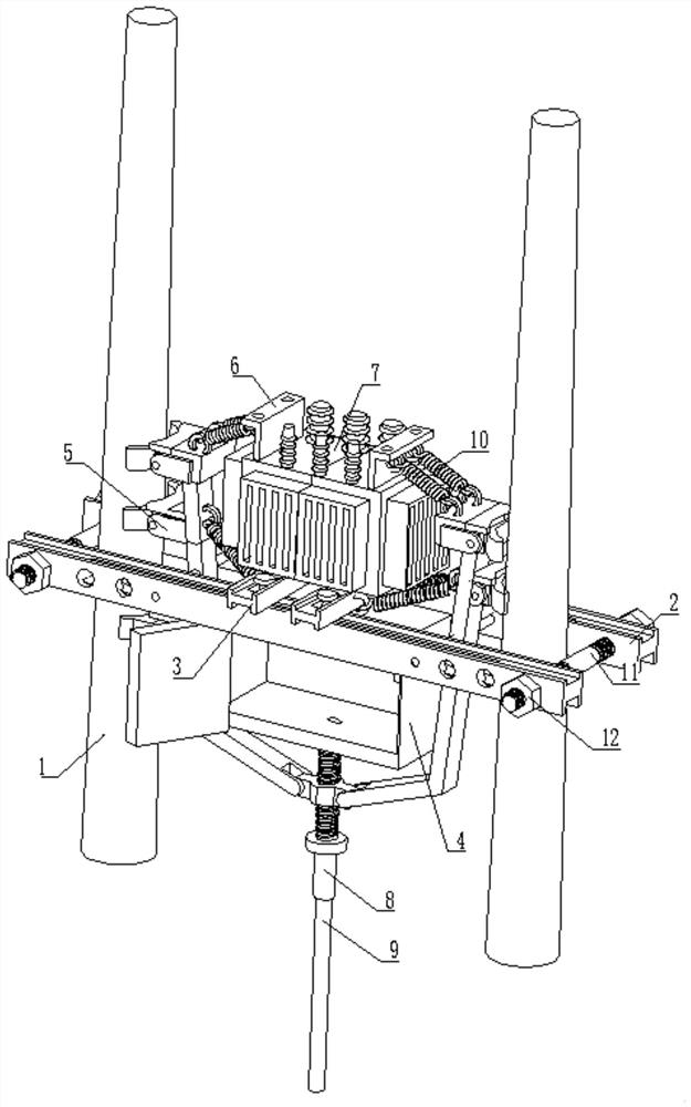
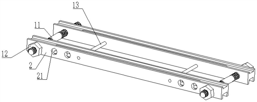
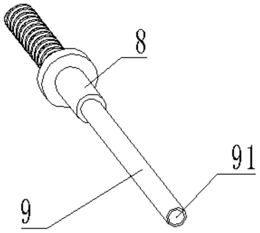
[0030] see Figure 1-4 , a transformation of a transformer on a pole, including a mounting pole 1, two beams 2 are arranged on the surface of the mounting pole 1, a locking rod 11 is inserted into the inside of the beam 2, and two locking rods are threaded on the surface of the locking rod 11 Tighten the nut 12, the inside of the beam 2 is slidingly connected with two longitudinal beams 3, the upper surface of the longitudinal beams 3 is connected with the transformer body 7 by bolts, the upper surface of the transformer body 7 is welded with two fixing plates 6, and the fixing plates 6 The surface is provided with a buffer mechanism 10, the bottom of the beam 2 is connected to the cabinet 4 by bolts, the bottom of the cabinet 4 is connected with a rotating rod 8, and the surface of the rotating rod 8 is provided with a mounting mechanism 5.

[0031] In this embodiment, the inside of the rotating rod 8 is slidingly connected with a grounding pipe 9. The design of the grounding...

Embodiment 2

[0042] Please refer to Figure 4-6 , on the basis of Embodiment 1, in this embodiment, the buffer mechanism 10 includes a first spring 101 and a second spring 104, one end of the first spring 101 is clamped with an upper pull ring 102, and the other end of the first spring 101 Clipped on the surface of the fixed plate 6, one end of the second spring 104 is clipped with a pull-down ring 103, the other end of the second spring 104 is clipped on the surface of the longitudinal beam 3, and the surfaces of the upper pull ring 102 and the pull-down ring 103 are respectively fixed It is connected to the surface of the upper splint 54 and the support rod 52 .

[0043] There are multiple sets of symmetrical springs, which reduce the vibration of the transformer during its own work, reduce the impact of the vibration force on the beam 2 and the longitudinal beam 3, further improve the stability of the overall mounting frame, and can relatively pull the transformer Tight fixation effect...


PUM


Abstract

The invention relates to the technical field of transformers, and discloses pole-mounted transformer modification which comprises a mounting column. Two cross beams are arranged on the surface of themounting column, locking rods are inserted into the cross beams, two locking nuts are in threaded connection with the surfaces of the locking rods, and two longitudinal beams are in sliding connectionwith the interiors of the cross beams. And the upper surface of the longitudinal beam is connected with a transformer body through bolts, two fixing plates are welded to the upper surface of the transformer body, buffer mechanisms are arranged on the surfaces of the fixing plates, and mounting mechanisms are arranged on the surfaces of the rotating rods. According to the pole-mounted transformermodification, the contact sleeves on the two clamping plates can be in extrusion contact with the surface of the mounting column to realize clamping and fixing, so that the loosening condition in themounting process can be reduced to a great extent, and the pole-mounted transformer modification is only tighter and tighter along with long-time use, so that the mounting stability of the transformeris improved to a great extent, thereby reducing the occurrence of potential safety hazards.

Description

technical field [0001] The invention relates to the technical field of transformers, in particular to a modification of a pole-mounted transformer. Background technique [0002] The transformer is a device that uses the principle of electromagnetic induction to change the AC voltage. The main components are the primary coil, the secondary coil and the iron core (magnetic core). The main functions are: voltage conversion, current conversion, impedance conversion, isolation, voltage stabilization (magnetic saturation transformer), etc., and can be divided into power transformers and special transformers according to their uses. [0003] With the rapid development of society, the role of transformers in human production activities is becoming more and more important, and the installation process of some transformers is very cumbersome, time-consuming and labor-intensive, and the flexibility is relatively poor. Intensity of vibration causes some installation bolts to loosen eas...

Claims


Application Information

Patent Timeline
Patent Type & Authority Applications(China)
IPC IPC(8): H01F27/06H01F27/02
CPCH01F27/02H01F27/06
Inventor 黄宏斌许瑞倩雷志翔沈兵兵周铭杰
Owner 浙江派尔电气有限公司
Features
  • R&D
  • Intellectual Property
  • Life Sciences
  • Materials
  • Tech Scout
  • Unparalleled Data Quality
  • Higher Quality Content
  • 60% Fewer Hallucinations
Learn More