Fixing structure for building electrical construction

A fixed structure and building electrical technology, applied in the direction of lifting devices, lifting frames, etc., can solve the problems of unreliable fixing, time-consuming and labor-intensive, easy to shake, etc., and achieve the effect of reducing weight, improving stability and increasing stability

Inactive Publication Date: 2018-11-27
LIAONING UNIVERSITY OF TECHNOLOGY
View PDF3 Cites 3 Cited by
  • Summary
  • Abstract
  • Description
  • Claims
  • Application Information

AI Technical Summary

Problems solved by technology

The small-sized electric meter box is generally installed on the corner wall of the corridor. Due to the narrow location, it is usually operated by two or more people. With the aid of simple small ladders and other tools, one pers

Method used


Image

  • Fixing structure for building electrical construction
  • Fixing structure for building electrical construction
  • Fixing structure for building electrical construction

Examples


Embodiment 1

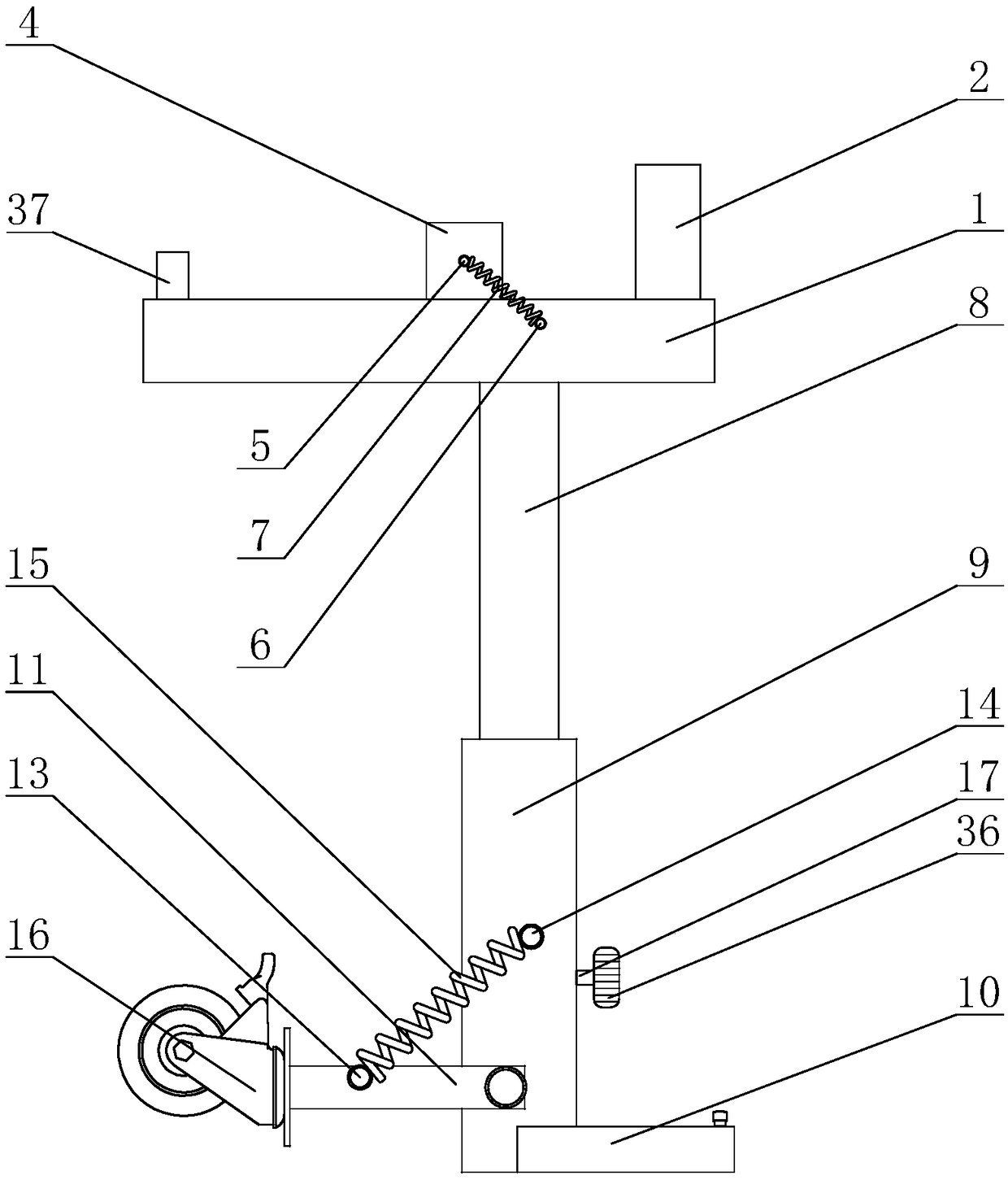
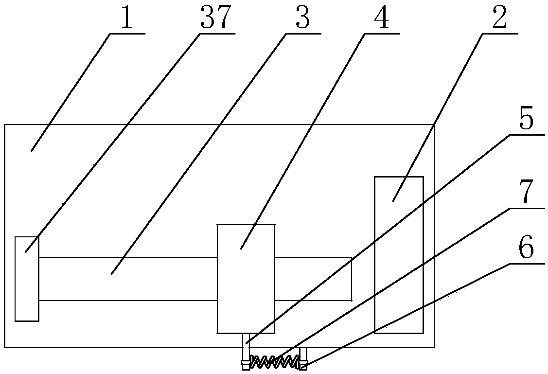
[0039] A fixed structure for electrical construction of a building, comprising a support plate 1, a fixing plate 2 is provided on the top side of the support plate 1, a slide groove 3 is provided on the top wall of the support plate 1, and a slider is provided in the slide groove 3, and A sliding plate 4 is provided at the top of the sliding block, and the sliding plate 4 is connected to the supporting plate 1 through a sliding block and a sliding groove 3 in a sliding manner. The sliding plate 4 is provided with a first connecting rod 5 on one side of the supporting plate 1. A second connecting rod 6 is provided. A first tension spring 7 is provided between the second connecting rod 6 and the first connecting rod 5. The second connecting rod 6 and the first connecting rod 5 are both connected to the first tension spring. 7 is hinged, the fixed plate 2 and the sliding plate 4 are located in the support plate 1 on the opposite side of the first tension spring 7, the bottom of the...

Embodiment 2

[0041] In this embodiment, on the basis of embodiment 1, the lifting device is replaced with a motor 27, which is fixedly connected to the bottom wall of the fixed rod 9, and a coupling 28 is provided on the output shaft of the motor 27. The shaft 28 is provided with a second screw 29 at one end away from the output shaft of the motor 27. A second nut 30 is mounted on the second screw 29. The second nut 30 is a cylindrical nut. The second guide rod 31 is provided with a second sliding block 32 at one end away from the second nut 30, and a second slide rail 33 is provided on the inner wall of the second fixed rod 9, and the second slide rail 33 is The sliding block 32 is adapted to each other, and a second connecting plate 34 is provided at the top of the second nut 30, and the second connecting plate 34 is fixedly connected to the bottom end of the sliding rod 8. The beneficial effect of this embodiment is that the invention adopts the rotation of the motor to adjust the liftin...

Embodiment 3

[0043] In this embodiment, on the basis of embodiment 1, the first bevel gear on the rotating rod is replaced with a spur gear, and the second bevel gear, the first screw, the first nut, the first slider, and the first slide rail are removed. Equivalent structure, a straight rack is provided on one side of the spur gear, the top of the straight rack is directly connected with the sliding rod, and the sliding lift of the sliding rod is realized through the gear rack structure.


PUM


Abstract

The invention discloses a fixing structure for building electrical construction, and relates to the technical field of electrical construction and installation. The structure comprises a supporting plate, a fixing plate is arranged on one side of the top of the supporting plate, a sliding groove is arranged on the top wall of the supporting plate, a sliding block is arranged in the sliding groove,a sliding plate is arranged at the top end of the sliding block, a first connecting rod is arranged on one side of the sliding plate, a second connecting rod is arranged on the supporting plate, a first tension spring is arranged between the second connecting rod and the first connecting rod; the bottom of the supporting plate is provided with a sliding rod; the bottom end of the sliding rod is sleeved with a fixing rod; the fixing rod is a hollow rod; a lifting device is arranged in the fixing rod; a supporting frame is arranged on one side of the fixing rod; the bottom of the supporting frame is on the same level with the bottom end of the fixing rod; one end of a adjusting rod is hinged with the fixing rod, a clamping groove is arranged on the supporting frame, a third connecting rod is arranged on the adjusting rod, a fourth connecting rod is arranged on the fixing rod, and a roller is arranged at one end of the adjusting rod, away from the fixing rod. The structure has the advantages that the labor intensity of an installer is reduced, and the stability degree of an electric meter box during installation is improved.

Description

Technical field [0001] The invention mainly relates to the technical field of electrical construction and installation, in particular to a fixed structure for electrical construction of a building. Background technique [0002] In construction engineering electricity, various electrical devices, such as various electrical control boxes, are often installed on the building wall. The small-sized meter box is generally installed on the corner wall of the corridor. Due to the narrow position, it is usually completed by two or more people together. A simple small ladder and other tools are assisted by one person to hold it for installation. One person to drill and fix the meter box is not only time-consuming and labor-intensive, but also the meter box to be installed is easily shaken by manpower, and the fixation is not reliable. Summary of the invention [0003] In order to solve the shortcomings of the prior art, the present invention provides a fixed structure for electrical constr...

Claims


Application Information

Patent Timeline
IPC IPC(8): B66F7/14B66F7/12B66F7/28
CPCB66F7/12B66F7/14B66F7/28
Inventor 孙晶高博
Owner LIAONING UNIVERSITY OF TECHNOLOGY
Why Eureka
Try Eureka