
High-voltage power transmission device

A transmission device and high-voltage technology, which is applied in the direction of circuit devices, electrical components, building types, etc., can solve the problems of short installation distance, slow installation speed, and large land occupation, and achieve a tight fit effect

Inactive Publication Date: 2021-03-09
CHONGQING BEIJING TECH RES & DEV
View PDF1 Cites 0 Cited by
  • Summary
  • Abstract
  • Description
  • Claims
  • Application Information

AI Technical Summary

Problems solved by technology

[0008] Through long-term research, we have solved the problems of heavy weight, inconvenient transportation and slow installation speed of utility poles and power tower poles using cement poles, and also solved the problem of short installation distance between utility poles or power tower poles or iron towers, and occupied The problem of a lot of land has also solved the safety problem of high-voltage wires being placed under the ground, and invented a high-voltage power transmission device for wireless long-distance transmission of high-voltage power

Method used


Image

  • High-voltage power transmission device
  • High-voltage power transmission device
  • High-voltage power transmission device

Examples


Embodiment Construction

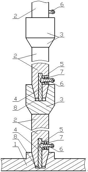
[0092] The high-voltage power transmission device of the present invention mainly includes two parts: a power transmission support frame and a plasma power transmission device;

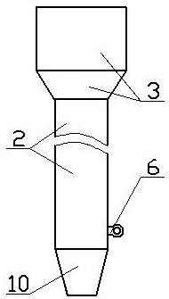
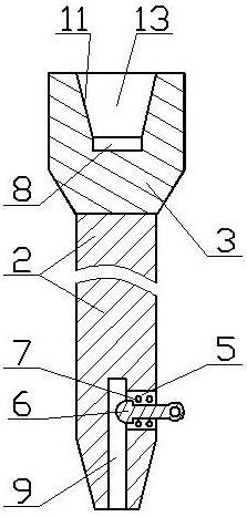
[0093] The transmission electric support frame mainly includes a base 1, a pillar body, a braking hole 5, a braking pin 6, a locking spring 7, a locking rod 4, a sliding hole 9, a braking groove, an outer tapered surface 10, and an inner tapered hole , inner cone surface 11;

[0094] The base 1 is fixedly installed on the base, and the locking rod 4 is fixed in the air gap groove 8 below the first inner tapered hole 12 in the middle of the base 1, and one end of the pillar body with the outer tapered surface 10 is inserted into the middle of the base 1 In the first inner tapered hole 12, the sliding hole 9 at the end of the outer tapered surface 10 ends is sleeved on the lock bar 4, and the brake head of the brake pin 6 locks the lock bar 4 in the brake groove on the lock bar; There is a second inner...


PUM


Abstract

The invention discloses a high-voltage power transmission device. An outer conical surface of the lower end of a strut body is inserted into a first inner conical hole in the middle of a base, and theouter conical surface of the upper strut body is inserted into a second inner conical hole of the lower strut body; after the outer conical surface is matched and fixed with the inner conical surfaceof the inner conical hole, the inner conical surface and the outer conical surface are automatically locked through a locking device, and the inner conical surface and the outer conical surface whichare tightly attached are not loosened, so the power transmission support frame is firm and reliable; the plasma conductive light beam emitter and the receiving conductive plate are installed on the power transmission supporting frame, the plasma conductive light beam emitter emits plasma conductive light beams and then receives high-voltage power remotely through the ion conductive light beam receiver, long-distance wireless high-voltage power transmission is achieved, the time for laying and erecting a high-voltage power transmission line is shortened, and working efficiency is improved; andlabor cost and material resource cost for laying the high-voltage line are reduced, and maintenance cost and use cost of high-voltage power transmission are reduced.

Description

[0001] The present invention is a divisional application of "Patent Application Number: 2014108245740; Invention Name: High-voltage Electric Transmission Device". technical field [0002] The invention relates to a high-voltage electric transmission device for electric grid transmission. Background technique [0003] Traditional high-voltage power transmission uses utility poles or power tower poles or iron towers to support high-voltage lines. The position of the original three-way high-voltage lines on the utility poles or iron towers must be changed every other distance. To stabilize the delivered voltage. [0004] At the same time, because the utility poles or power tower poles or iron towers have to support the weight of the high-voltage line and bear the tension of the high-voltage line, and the installation between the utility poles or power tower poles or iron towers is not in a straight line, and the installation of the high-voltage line In order to prevent the hig...

Claims


Application Information

Patent Timeline
Patent Type & Authority Applications(China)
IPC IPC(8): H02J50/00H02J50/30E04H12/00E04H12/18
Inventor 不公告发明人
Owner CHONGQING BEIJING TECH RES & DEV
Learn More