Rotating shaft structure and driving motor

A shaft structure and rotor technology, applied in the direction of magnetic circuit rotating parts, magnetic circuit shape/style/structure, electric components, etc., can solve the problems of difficult cooling system, unsolved rotor cooling problem, limited and other problems

Inactive Publication Date: 2021-03-09
恒大恒驰新能源汽车研究院(上海)有限公司
View PDF5 Cites 4 Cited by
  • Summary
  • Abstract
  • Description
  • Claims
  • Application Information

AI Technical Summary

Problems solved by technology

At present, the cooling system of the new energy motor is still only focused on the cooling of the stator. Since the rotor is a rotating body and is limited by the design defects of the traditional rotor structure, it is difficult to add a cooling system to the rotor. For this reason, the problem of rotor cooling has not been effectively resolved

Method used


Image

  • Rotating shaft structure and driving motor
  • Rotating shaft structure and driving motor
  • Rotating shaft structure and driving motor

Examples


Embodiment Construction

[0022] In order to make the above objects, features and advantages of the present invention more comprehensible, specific implementations of the present invention will be described in detail below in conjunction with the accompanying drawings. In the following description, numerous specific details are set forth in order to provide a thorough understanding of the present invention. However, the present invention can be implemented in many other ways different from those described here, and those skilled in the art can make similar improvements without departing from the connotation of the present invention, so the present invention is not limited by the specific embodiments disclosed below.

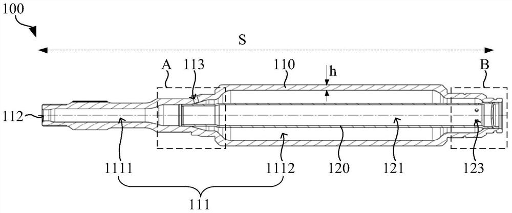
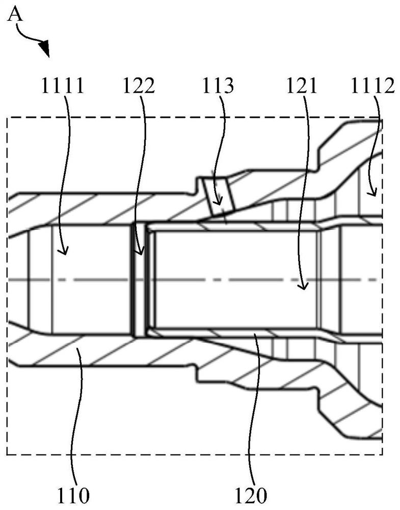
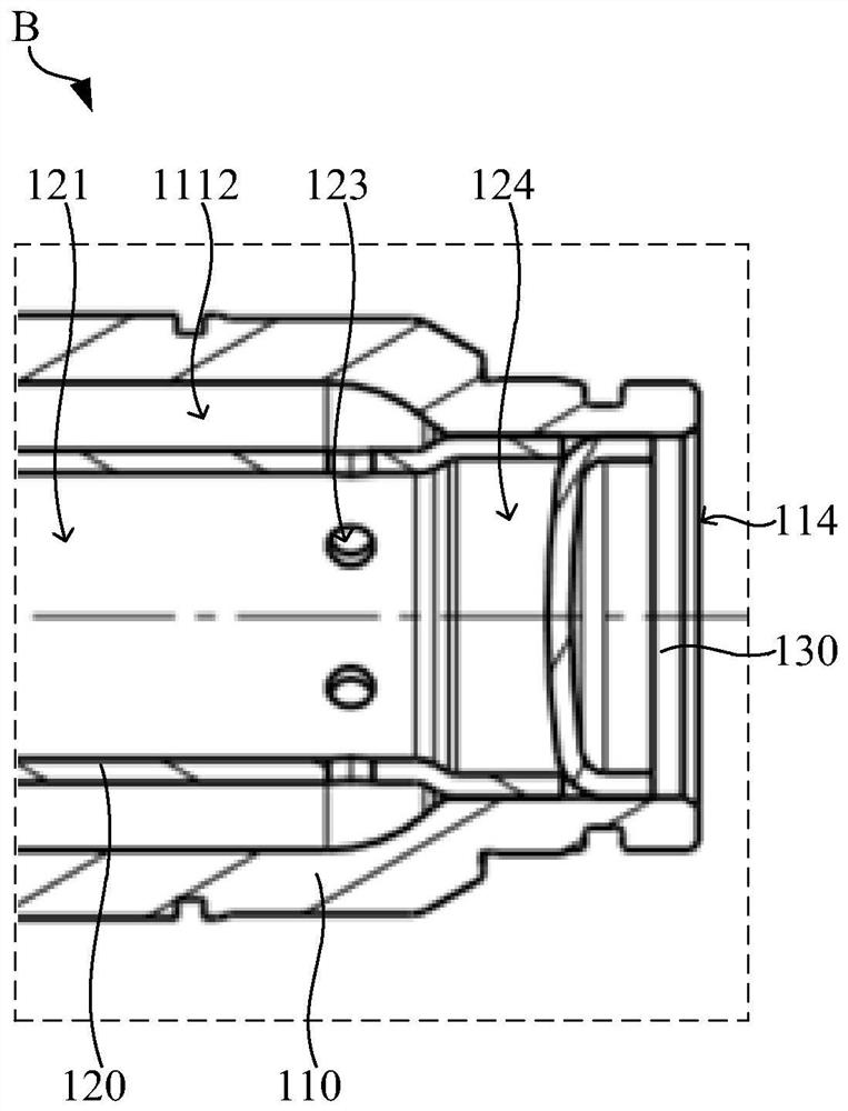
[0023] In one example, please refer to figure 1 , figure 2 and image 3 , a rotating shaft structure 100 , the rotating shaft structure 100 includes: a shaft body 110 and a deflector 120 . The shaft body 110 is provided with a cooling chamber 111 . The shaft body 110 is provided with...


PUM


Abstract

The invention relates to a rotating shaft structure and a driving motor. The rotating shaft structure comprises a shaft body and a flow guide part. The flow guide part is sleeved with the shaft body,and the problem that a cooling system is difficult to install due to rotor rotation is solved. And meanwhile, the flow guide part is discharged into the cooling cavity from the flow guide cavity through the flow guide part, so that the coolant continuously flows from the middle to the periphery, the coolant in the cooling cavity is always in a flowing state, the heat exchange efficiency between the coolant and the shaft body is improved, and the cooling effect of the rotor is improved. Besides, the rotating shaft structure is internally sleeved with the flow guide part, so that a multi-layer heat exchange interface is formed in the cooling cavity, through the multi-layer heat exchange interface, the effective residence time of the coolant in the shaft body is prolonged, sufficient heat exchange of the coolant is guaranteed, and the cooling effect of the rotor is further improved. Besides, the shaft body and the flow guide part are both designed to be hollow, so that the overall weightof the rotating shaft structure is effectively reduced, and the high-power density requirement of the driving motor is met.

Description

technical field [0001] The invention relates to the technical field of motors, in particular to a rotating shaft structure and a driving motor. Background technique [0002] With the development of new energy vehicle drive motors, the power density of motors is getting higher and higher, the temperature rise requirements of motors are becoming more and more stringent, and the cooling system requirements of motors are also becoming more and more stringent. At present, the cooling system of the new energy motor is still only focused on the cooling of the stator. Since the rotor is a rotating body and is limited by the design defects of the traditional rotor structure, it is difficult to add a cooling system to the rotor. For this reason, the problem of rotor cooling has not been effectively resolved. Contents of the invention [0003] Based on this, it is necessary to provide a rotating shaft structure and a driving motor to achieve a stable cooling effect and effectively s...

Claims


Application Information

Patent Timeline
Patent Type & Authority Applications(China)
IPC IPC(8): H02K1/32H02K9/19H02K7/00
CPCH02K1/32H02K9/19H02K7/003H02K2213/03
Inventor 张鹏罗旋夏继孔勇进
Owner 恒大恒驰新能源汽车研究院(上海)有限公司
Why Eureka
Try Eureka