
Cutting equipment for three-edged auger stem

A technology of auger drill pipe and cutting equipment, which is applied in the field of drill pipe processing, can solve the problems of increasing labor costs of enterprises, unfavorable high-efficiency production of enterprises, manual operation of manpower, etc., and achieves the reduction of labor costs of enterprises, high degree of equipment integration, and improvement of processing the effect of the effect

Inactive Publication Date: 2021-03-12
HUAIBEI LINGUANG DRILLING ELECTROMECHANICAL ENG
View PDF0 Cites 0 Cited by
  • Summary
  • Abstract
  • Description
  • Claims
  • Application Information

AI Technical Summary

Problems solved by technology

[0004] The invention proposes a cutting device for triangular helical drill pipes, which solves the problem that the existing triangular helical drill pipes need manual operation when cutting, which increases the labor cost of the enterprise and is not conducive to the efficient production of the enterprise.

Method used


Image

  • Cutting equipment for three-edged auger stem
  • Cutting equipment for three-edged auger stem
  • Cutting equipment for three-edged auger stem

Examples


Embodiment Construction

[0021] The following will clearly and completely describe the technical solutions in the embodiments of the present invention with reference to the accompanying drawings in the embodiments of the present invention. Obviously, the described embodiments are only some, not all, embodiments of the present invention.

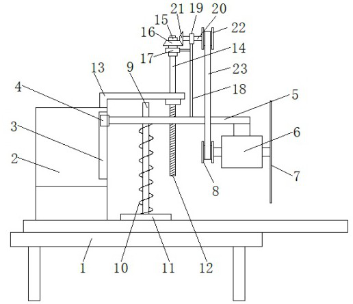
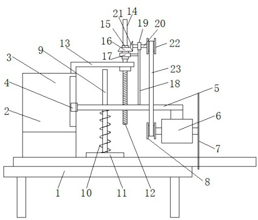
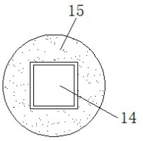
[0022] refer to Figure 1-3 , a cutting device for triangular auger drill rods, comprising a placement plate 1, the top of the placement plate 1 is fixedly connected with a fixed seat 2, the right side of the fixed seat 2 is slidably connected with a movable rod 5, and the right side of the bottom of the movable rod 5 is Fixedly connected with a double-axis motor 6, the fixed sleeve of the output shaft at the right end of the double-axis motor 6 is provided with a cutting wheel 7, and the inner movable sleeve of the movable rod 5 is provided with a pressing mechanism. The fixed plate 13 is fixedly connected, and the inner movable sleeve of the fixed plate 13 is provi...


PUM


Abstract

The invention discloses cutting equipment for a three-edged auger stem, and relates to the technical field of drill stem machining. The following scheme is provided in order to solve the problems thatwhen an existing three-edged auger stem is cut, manual operation is needed, the labor cost of an enterprise is increased, and efficient production of the enterprise is affected. A placement plate isincluded. A fixed seat is fixedly connected to the top of the placement plate, a movable rod is slidably connected to the right side of the fixed seat, a double-shaft motor is fixedly connected to theright side of the bottom of the movable rod, a cutting wheel fixedly sleeves an output shaft at the right end of the double-shaft motor, and a pressing mechanism is movably arranged inside the movable rod in a sleeving mode. A fixed plate fixedly connected with the top of the fixed seat is arranged above a pressing mechanism, and a lifting mechanism is movably arranged in the fixed plate in a sleeved mode. The same motor is conveniently adopted for driving, one machine has multiple purposes, automatic lifting is facilitated to complete positioning cutting, manual operation is not needed, thelabor cost of an enterprise is reduced, and the machining effect is improved.

Description

technical field [0001] The invention relates to the technical field of drill pipe processing, in particular to a cutting device for triangular helical drill pipes. Background technique [0002] The drill pipe is a steel pipe with threads at the end, which is used to connect the surface equipment of the drilling rig and the drilling and grinding equipment or the bottom hole device at the bottom of the drilling well. The purpose of the drill pipe is to transport the drilling mud to the drill bit and together with the drill bit to raise, lower or rotate the bottom hole device. Drill pipes must be able to withstand huge internal and external pressure, twisting, bending and vibration. Drill pipes are widely used, and many machining processes need to use drill pipes for drilling. [0003] During the processing of the existing triangular helical drill pipe, different processing procedures are required, such as grinding, cutting and grinding, etc., and when cutting operations, cutt...

Claims


Application Information

Patent Timeline
Patent Type & Authority Applications(China)
IPC IPC(8): B23D19/00B23D33/02B23Q5/28
CPCB23D19/00B23D33/02B23Q5/28
Inventor 贺萌萌江海杨维平任磊磊林长明周船
Owner HUAIBEI LINGUANG DRILLING ELECTROMECHANICAL ENG
Learn More