Rust removal device for mechanical production

A technology for machinery and rotating electrical machines, applied in the field of rust removal devices for mechanical production, can solve the problems of inability to mix rust removal liquid and rusted metal parts, difficult to popularize and apply, and poor rust removal effect, so as to improve the rust removal effect and ensure Rust removal effect, good contact effect

Inactive Publication Date: 2021-03-12
李卓亮
View PDF0 Cites 0 Cited by
  • Summary
  • Abstract
  • Description
  • Claims
  • Application Information

AI Technical Summary

Problems solved by technology

[0003] The existing rust removal equipment for metal parts has poor rust removal effect and cannot fully mix the rust removal liquid and rusted metal parts, so it is difficult to be popularized and applied

Method used


Image

  • Rust removal device for mechanical production
  • Rust removal device for mechanical production
  • Rust removal device for mechanical production

Examples


Embodiment 1

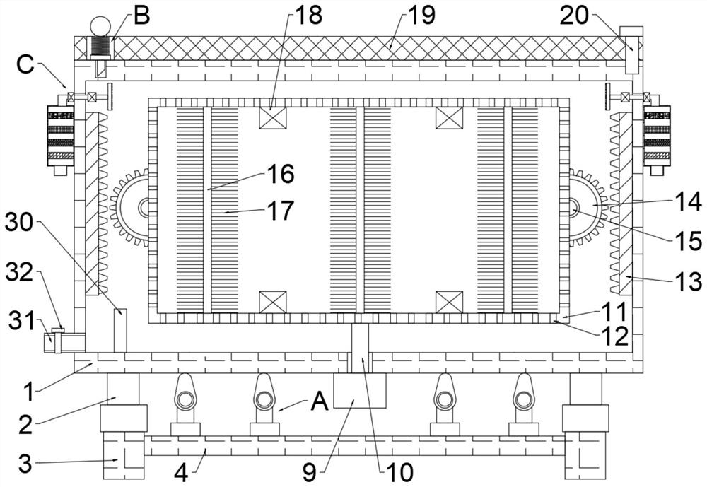
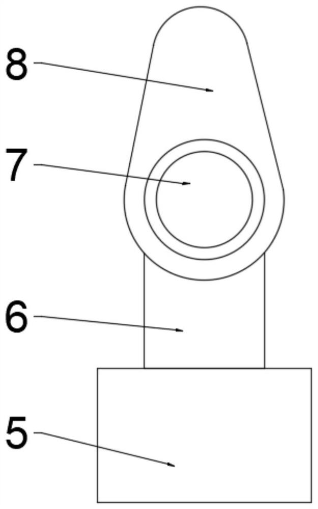
[0030] see Figure 1 to Figure 5 , a rust removal device for mechanical production, including a base 1, a device box 41 is arranged on the base 1, a cleaning cylinder 11 is arranged in the device box 41, and a telescopic rod 2 is symmetrically arranged under the base 1 One end of the telescopic rod 2 away from the base 1 is fixedly connected to the support leg 3, the support leg 3 is provided with a crossbeam 4, the crossbeam 4 is fixedly connected to the support leg 3, and the crossbeam 4 is provided with several motors 5, so There are at least four motors 5, the motors 5 are evenly distributed on the beam 4, the output end of the motor 5 is fixedly connected to the turbine 6, the turbine 6 is connected to the worm 7, and the end of the worm 7 away from the turbine 6 is connected to the cam 8 , the cam 8 is movably connected to the device box 41, the cleaning cylinder 11 is provided with a through hole 12, the through hole 12 runs through the cleaning cylinder 11, the through...

Embodiment 2

[0037] see Figure 1 to Figure 6 , a rust removal device for mechanical production, including a base 1, and also includes an upper chute 33, a slide bar 34 and a lower chute 35, the base 1 is provided with a device box 41, and the device box 41 is provided with Cleaning cylinder 11, a telescopic rod 2 is symmetrically arranged under the base 1, and one end of the telescopic rod 2 away from the base 1 is fixedly connected to a support leg 3, and a crossbeam 4 is arranged on the support leg 3, and the crossbeam 4 is fixedly connected to the support leg 3. Several motors 5 are arranged on the beam 4, at least four motors 5 are arranged, and the motors 5 are evenly distributed on the beam 4. The output ends of the motors 5 are fixedly connected to the turbine 6, and the turbine 6 Connect the worm 7, the end of the worm 7 away from the turbine 6 is connected to the cam 8, the cam 8 is movably connected to the device box 41, the cleaning cylinder 11 is provided with a through hole 1...


PUM


Abstract

The invention discloses a rust removal device for mechanical production, and belongs to the technical field of machining equipment. The rust removal device solves the problem of poor rust removal effect of existing mechanical part rust removal. The rust removal device is technically characterized by comprising a base, wherein a device box body is arranged on the base, a cleaning cylinder is arranged in the device box body, and telescopic rods are symmetrically arranged below the base; the ends, away from the base, of the telescopic rods are fixedly connected with supporting legs, the supporting legs are provided with a cross beam, the cross beam is fixedly connected with the supporting legs, the cross beam is provided with at least four motors, the motors are evenly distributed on the cross beam, the output ends of the motors are fixedly connected with worm wheels, and the worm wheels are connected with worms; and the ends, away from the worm wheels, of the worms are connected with cams, the cams are movably connected with the device box body, and through holes are formed in the cleaning cylinder, penetrate through the cleaning cylinder and are evenly distributed in the periphery of the cleaning cylinder. The beneficial effect of being good in rust removal effect is achieved.

Description

technical field [0001] The invention relates to the technical field of mechanical processing equipment, in particular to a derusting device for mechanical production. Background technique [0002] During the processing of hardware products, for example, the surface of the pipe body (water pipe, automobile exhaust pipe, heating pipe, etc.) is prone to rust due to improper preservation. If it is not treated, it will have a serious impact on its performance. Metal material refers to the general designation of metal elements or materials with metal characteristics mainly composed of metal elements. Metal materials include pure metals, alloys, intermetallic compounds and special metal materials. Most of the mechanical materials are metal materials. Metal sheets are the most commonly used building materials in construction projects. After a long period of storage, the surface of metal sheets usually has rust. Before use, it is often necessary to repair the metal sheets. The surf...

Claims


Application Information

Patent Timeline
IPC IPC(8): B24B27/033B24B1/04B24B31/027B24B31/03B24B31/12B24B27/00B24B47/00B24B47/20C23G3/00
CPCB24B1/04B24B27/0076B24B27/033B24B31/027B24B31/03B24B31/12B24B47/00B24B47/20C23G3/00
Inventor 李卓亮
Owner 李卓亮
Why Eureka
Try Eureka